
 WhatsApp: +86 16626708626
 Email:
  Phone: +86 16626708626
Description
2. Product Core Brief
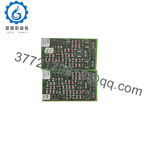
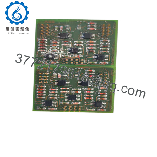
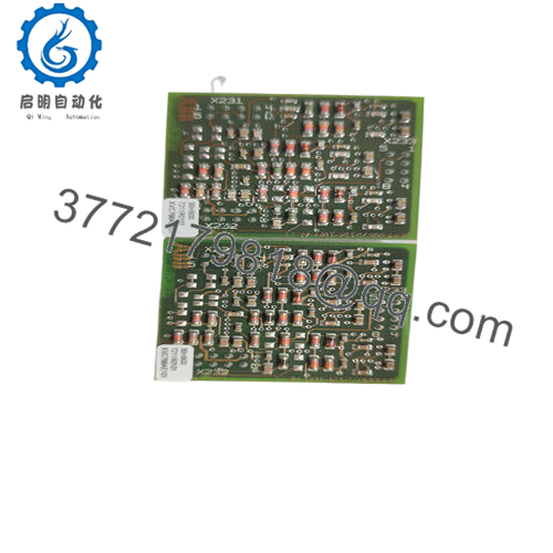
- Model: 3BHB015651P0001
- Brand: ABB
- Series: ABB Rectifier & Power Conversion Modules
- Core Function: DC link rectification for MV drives
- Product Type: Power Semiconductor Module
- Key Specs: High current capability; MV-rated blocking; press-pack design
- Condition: New Original / New Surplus
3. Key Technical Specifications
| Parameter | Value |
|---|---|
| Module Type | DC Link Rectifier / Power Stage |
| Technology | Press-pack diodes/thyristors (depending on subvariant) |
| Target Application | Medium-voltage drives, rectifier bridges |
| Voltage Rating | MV-class (verify exact kV rating via datasheet) |
| Current Rating | kA-level continuous (platform dependent) |
| Mounting Type | Clamped press-pack assembly |
| Cooling Method | Heatsink, liquid or forced-air (platform dependent) |
| Operating Temp | Typically −40 to +125°C junction (confirm per datasheet) |
| Compliance | IEC 60747 semiconductor standard |
| Insulation Level | Designed per MV insulation coordination specs |
⚠️ Refer to the precise ABB datasheet for exact voltage and current limits. Ratings vary by sub-variant and installation configuration.

- 3BHB015651P0001
4. Product Introduction
The ABB 3BHB015651P0001 is a high-power DC link rectifier/power stage module intended for medium-voltage AC-to-DC conversion within industrial drives and power systems. It integrates press-pack semiconductor elements suitable for continuous high-current rectification duties.
This module is selected in applications where sustained high current and reliable blocking voltage are mandatory. Compared with discrete assemblies, this unit provides a compact press-pack design favorable for serviceability and predictable thermal performance. Verify exact voltage and current ratings against your drive family’s requirements.
5. Installation & Configuration Guide
This module is part of a high-voltage power conversion assembly. Physical installation must respect torque, cooling, and insulation specifications.
Stage 1: Pre-Installation Preparation (10–15 minutes)
⚠️ Safety First
- Notify operations of planned downtime and isolate MV supply.
- Lock out/tag out (LOTO) all DC-link and AC mains breakers.
- Confirm capacitor discharge with a multimeter; wait a minimum of 10 minutes for DC link capacitors to bleed off.
- Ensure proper PPE for high-voltage work.
Tools Required
- ESD wrist strap
- Insulated torque wrench (calibrated)
- Fluke 115 multimeter or equivalent
- Lint-free cleaning wipes
- Label markers and smartphone for documentation
Document Existing Setup
- Photograph busbar orientation and clamping arrangement.
- Capture wiring diagrams and gate/auxiliary connections.
Stage 2: Removing the Old Module (10 minutes)
- Confirm DC-link voltage is zero with a meter at the module terminals.
- Disconnect gate/auxiliary wiring carefully; retain labels.
- Loosen clamping bolts in a cross pattern to relieve pressure evenly.
- Remove the module straight out; avoid twisting.
⚠️ Inspect busbars and heatsink faces for pitting or contamination. Clean if required.
⚠️ Retain the old module until the system is fully commissioned.
Stage 3: Installing the New Module (10 minutes)
- Wear ESD protection.
- Verify part number: 3BHB015651P0001 matches the old unit.
- Clean heatsink surfaces; apply OEM-specified thermal interface as required.
- Insert module with correct polarity and alignment.
- Tighten clamping bolts using cross-pattern sequence to the OEM torque spec.
- Reconnect gate/auxiliary wiring using original labels.
Self-Checklist
- Model number verified
- Proper polarity alignment
- Correct torque on fasteners
- Wiring integrity confirmed
Stage 4: Power-On & Testing (10–20 minutes)
Pre-Power Validation
- Check DC-link for shorts.
- If applicable, perform a megger test on isolated auxiliary circuits.
Power-On Sequence
- Bring control power up first.
- Monitor drive diagnostics panel for errors.
- Engage DC bus per drive vendor start-up sequence.
- Confirm rectifier output voltage is within expected range.
- Perform a dry-run without load.
⚠️ If rectifier undervoltage or overcurrent faults occur, de-energize immediately and recheck bus connections and cooling paths.
6. Frequently Asked Questions (FAQ)
Q1: Can this module be replaced while the drive is powered?
No. This is part of a medium-voltage rectification stage. Hot-swapping risks severe injury and equipment damage. Always de-energize and discharge the DC link before servicing.
Q2: Is ABB 3BHB015651P0001 obsolete?
This specific module may not be in active OEM production depending on your drive platform generation. Many units are available as surplus stock. Confirm status with official ABB documentation if long-term support matters.
Q3: What does “New Original / New Surplus” mean?
It means unused OEM-manufactured stock sourced from surplus inventory. Units should be tested and verified, with traceability documentation where available.
Q4: Will I lose drive programming if I swap this?
No. Drive logic and parameters are stored in the drive controller (PLC or embedded controller), not in the rectifier module.
Q5: How do I verify I ordered the right part?
Check these points before ordering:
- Exact drive model and variant
- Voltage class requirements
- Continuous and peak current ratings
- Mechanical footprint
Always cross-reference with your drive’s BOM.
Q6: Why is your price lower than OEM list?
Surplus inventory often prices below OEM list due to availability and market dynamics. Traceability and condition verification are critical before purchase.


