
 WhatsApp: +86 16626708626
 Email:
  Phone: +86 16626708626
Description
2. Product Core Brief
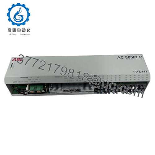
- Model: PPD103B01 (3BHE020455R0001)
- Brand: ABB
- Series: ABB Industrial Drive Control Platform (ACS/Excitation systems)
- Core Function: Digital drive control and signal processing
- Product Type: Drive Control Processor Module
- Key Specs: High-speed DSP control, industrial communication interface, rack-mounted board
- Condition: New Original / New Surplus
3. Key Technical Specifications
| Parameter | Value |
|---|---|
| Manufacturer | ABB |
| Model | PPD103B01 |
| Order Number | 3BHE020455R0001 |
| Product Type | Drive Control Processor Module |
| Application | Industrial drive systems and excitation control |
| Processor Type | Digital signal processor (DSP-based control) |
| Communication Interfaces | Internal drive bus, industrial control interface |
| Mounting Method | Rack-mounted PCB module |
| Power Supply | Backplane powered (from control rack) |
| Operating Temperature | 0 to +55 °C typical industrial rating |
| Storage Temperature | −25 to +70 °C |
| Approx. Weight | ~0.6 kg |
| Compliance | Designed for ABB drive systems per IEC industrial standards |
Note: Exact electrical ratings may vary depending on the host drive platform. Always verify against the ABB hardware manual for the specific drive cabinet.
4. Product Introduction
The ABB PPD103B01 (3BHE020455R0001) is a processor control module used in ABB industrial drive systems and excitation platforms. It performs real-time signal processing, drive regulation logic, and communication with higher-level controllers in power conversion cabinets.
In field deployments of ABB medium-voltage and high-power drive systems, this module acts as the computational core responsible for control loop execution and system coordination. Plants typically keep spare PPD series boards because drive downtime in rolling mills, turbines, or large pump systems quickly escalates into production loss.

- 3BHE020455R0001 PPD103B01
5. Installation & Configuration Guide
Stage 1 — Pre-Installation Preparation (Estimated time: 10 minutes)
⚠️ Safety First
- Notify operations that the drive cabinet will be offline.
- Place the drive system into a safe shutdown state.
- Lock out/tag out (LOTO) incoming power sources.
- Wait at least 5 minutes for DC bus capacitors to discharge.
Tools Required
- ESD wrist strap
- PH1 screwdriver
- Digital multimeter (Fluke 115 or equivalent)
- Wire labels
- Smartphone for documentation
Data Backup
- Export current drive parameters and control configuration from the ABB commissioning software.
- Document communication addresses and node IDs.
- Photograph all connector positions and DIP switches before removing the board.
Stage 2 — Removing the Old Module (Estimated time: 5–8 minutes)
- Open the drive control cabinet and remove the protective panel.
- Label and disconnect all ribbon cables or connectors. Do not pull by the cable.
- Release the board retaining clips or guide rails.
- Pull the module straight out of the rack to avoid bending backplane pins.
- Inspect the rack:
- Check for dust accumulation
- Look for bent backplane contacts
- Verify no debris inside the card guides
⚠️ Important: Keep the old module nearby until the replacement is fully operational. It serves as your configuration reference.
Stage 3 — Installing the New Module (Estimated time: 5 minutes)
- Wear an ESD strap and work on an ESD-safe surface.
- Verify part numbers match exactly:
- PPD103B01
- 3BHE020455R0001
- Configuration Clone (Critical Step)
Replicate any DIP switches or configuration jumpers from the original board.
❗ This is the most common installation mistake.
I have seen engineers install a new board with factory defaults and spend hours chasing communication faults.
- Slide the module carefully into the rack guide rails.
- Push until the board fully seats into the backplane connector.
- Reconnect all cables using correct orientation.
Self-Checklist
- Part number verified
- DIP switches match old module
- Connectors fully seated
- Retaining clips secured
Stage 4 — Power-On & Testing (Estimated time: 10 minutes)
Pre-Power Check
- Use a multimeter to verify no short between 24 V rail and ground.
Power-On Procedure
- Restore power to the control rack only first.
- Observe board status LEDs.
Typical behavior:
- Green RUN LED: Controller running normally
- Red FAULT/ERR LED: Configuration or hardware problem
- Connect commissioning software to the drive system.
- Verify:
- Communication handshake
- Firmware version
- Controller recognition
- Restore drive parameters if required.
- Perform a dry run of control logic and I/O signals before enabling the full drive system.
⚠️ Troubleshooting Tip
If communication fails immediately after installation:
- Verify node address settings
- Confirm firmware compatibility
- Check that ribbon cables are not offset by one pin
6. Frequently Asked Questions (FAQ)
Q1: Can I hot-swap the ABB PPD103B01 module?
No. This board is not designed for hot swapping.
Pulling it under power can damage both the board and the drive control rack. Always shut down the cabinet and follow lockout procedures before removal.
Q2: Is the PPD103B01 an obsolete model?
Yes, in many installations this board is no longer in active production by ABB. However, large numbers remain in service in heavy industrial drives. Spare inventory usually comes from new surplus stock or carefully tested refurbished units.
Plants running older drive cabinets often purchase two spares to avoid future downtime.
Q3: Will I lose my drive configuration when I replace this board?
Usually no, but it depends on the drive architecture.
Some ABB systems store parameters in separate memory modules or engineering stations, while others rely on the processor board itself. Always export the configuration before removal.
Q4: Why do identical model numbers sometimes fail to communicate after installation?
The usual cause is firmware revision mismatch.
I have seen drives where the old board ran firmware V2.x, and the replacement shipped with V3.x. The communication protocol changed slightly, and the system refused to initialize.
Always record the firmware version of the old board before replacement.
Q5: Why is surplus stock cheaper than buying directly from the OEM?
OEM factories price spare parts based on long-term lifecycle support, not just hardware cost.
Surplus distributors typically sell inventory from:
- Project overstock
- Warehouse liquidation
- Decommissioned systems
The hardware is genuine, but supply is limited.
Q6: How do you verify these modules before shipping?
We follow a structured inspection process:
Inbound inspection
- Serial number verification
- Visual inspection for corrosion or solder rework
Electrical tests
- Insulation resistance test using 500 V Megger (>10 MΩ)
- Ground continuity check
Functional testing
- Installed in a compatible ABB drive control rack
- Power-on verification and communication handshake
- Continuous 24-hour powered run
Final QC
- ESD packaging
- Anti-static bag + foam protection
- QC label with inspection date
Test photos and videos are available if the buyer requests them.


