
 WhatsApp: +86 16626708626
 Email:
  Phone: +86 16626708626
Description
- Product Core Brief
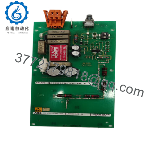
- Model: KS D211 A101 (3BHE024313R0101)
- Brand: ABB
- Series: KS D211 (Input Coupling family)
- Core Function: Couples and conditions input signals
- Product Type: Input coupling unit / interface module
- Key Specs: Signal isolation/conditioning for DCS/drive systems, PCB form factor
- Condition: New Original / New Surplus
- ⚠️ Obsolete Model – Limited Stock Available
- Key Technical Specifications
- ABB Type Designation: KS D211 A101
- Function: Input signal coupling/isolation (analog/digital to control system)
- Mounting: Typically DIN rail or rack slot in ABB systems
- Power Supply: Likely 24 V DC nominal (common for KS series interfaces – verify label)
- Input Channels: Multiple (exact count varies; often 8–16 points or grouped)
- Isolation: Galvanic isolation between field and system side
- Signal Types: Supports voltage/current inputs, possibly dry contacts
- Operating Temperature: −20 to +60 °C typical for ABB modules
- Protection Class: IP20
- Dimensions: Compact PCB (approx. 100–200 mm height, standard width)
- Weight: Approx. 0.2–0.5 kg
- Communication/Interface: Passive coupling (no fieldbus standard; wired to backplane or terminals)
- Product Introduction
The ABB 3BHE024313R0101 (KS D211 A101) is an input coupling unit that interfaces field signals into ABB control or excitation systems. It provides reliable signal conditioning, isolation, and transfer for analog or discrete inputs in industrial environments.
Maintenance teams rely on this module in legacy setups for its straightforward integration and proven signal integrity in noisy plant conditions. It reduces ground loop issues and protects controllers from field transients, making it a common spare in DCS racks or drive cabinets where direct wiring would risk noise or damage.
- Installation & Configuration Guide
Stage 1: Pre-Installation Preparation (15–20 min) ⚠️ Safety First: Coordinate downtime with operations. Lock out/tag out power to the rack/system. Wait 5 minutes for discharge. Tools Required: Grounded ESD wrist strap, PH1/PH2 screwdriver, multimeter, wire labels, smartphone for photos. Data Backup: Photograph module front (LEDs, terminals), backplane connections, and any jumpers/DIP switches. Document wiring to field inputs and system side.
Stage 2: Removing the Old Module (10 min)
- Power down rack.
- Label and disconnect field and system wiring (use torque driver; avoid pulling wires).
- Release locking tabs or screws; pull module straight out to protect pins.
- Inspect backplane connectors for bent pins, dust, or corrosion. ⚠️ Note: Retain old module for reference until new one operates fault-free.
Stage 3: Installing the New Module (15 min)
- Wear ESD strap. Confirm exact match (3BHE024313R0101, KS D211 A101).
- Configuration Clone (Crucial): Mirror any jumpers, DIP switches, or terminal assignments from photos (e.g., input range selectors, addressing if present).
- Insert into slot; ensure full seating and tab lock.
- Reconnect wiring per labels (torque terminals 0.5–0.8 Nm typical). Self-Checklist: [ ] Jumpers/DIPs match, [ ] Wiring polarity/sequence correct, [ ] Module seated and locked.

- 3BHE024313R0101
Stage 4: Power-On & Testing (20–30 min) Pre-Power Check: Multimeter for no shorts on power rails and correct polarity. Power-On Steps:
- Power rack (no field signals first).
- Observe LEDs (power ON, no fault; status per manual).
- Apply test inputs (e.g., 4–20 mA simulator or dry contact).
- Verify signals reach controller (use HMI or programming tool to check values).
- Run full system test under load. ⚠️ Troubleshooting Note: No power LED = check supply fuse/rail. Erroneous readings = jumper mismatch or loose terminal. Fault LED = possible firmware/compatibility issue with host system.
- Frequently Asked Questions (FAQ)
Can this input coupling unit be hot-swapped? No. Power down the rack first. Live removal risks backplane damage, signal corruption, or module failure. I’ve seen a partial swap cause intermittent faults that took hours to trace.
Is this model obsolete, and is your stock genuinely new? Yes, KS D211 A101 / 3BHE024313R0101 is discontinued, with only surplus or aftermarket stock left as of 2026. Our units are new original or surplus from verified sources – we supply photos, serial traceability, and basic power-on/continuity test reports.
What is the direct replacement if this is out of stock? Check KS D211 B101 (3BHE022455R1101) or later revisions for potential compatibility. For newer systems, ABB may recommend updated interface modules from current lines. Always verify pinout, signal specs, and host system compatibility via datasheet before swap.
Will swapping the module require re-configuration or lose settings? Usually no firmware/settings in the module itself – configuration lives in the controller or jumpers. But photograph all jumpers/DIPs before removal and replicate exactly. Mismatch can cause wrong scaling or no signal pass-through.
Why is the price lower than original ABB pricing? Discontinued surplus from excess inventory or decommissioned systems – genuine ABB part, not rebuilt. We perform visual inspection, serial verification, and functional testing (power-up, LED check, basic signal pass) before shipping. You get tested hardware faster and cheaper than hunting OEM remnants.


