
 WhatsApp: +86 16626708626
 Email:
  Phone: +86 16626708626
Description
2. Product Core Brief
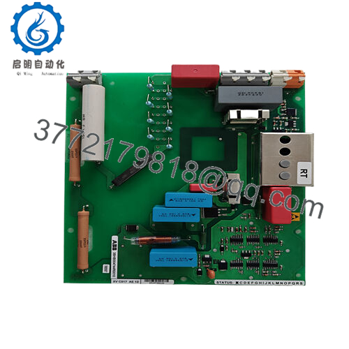
- Model: LTC745A101 (3BHE039905R0101)
- Brand: ABB
- Series: ABB Drive / Excitation Electronics (3BHE series)
- Core Function: Overvoltage crowbar protection
- Product Type: Crowbar Circuit Board
- Key Specs: Compact PCB form, thyristor-based shunt, DC link protection
- Condition: New Original / New Surplus
3. Key Technical Specifications
- Dimensions: Approx. 2.2 cm × 12.4 cm × 12.6 cm (from supplier data)
- Weight: 0.1 kg (typical for this form factor)
- Mounting: Plug-in board for ABB drive rack or inverter stack
- Primary Function: Crowbar thyristor trigger for overvoltage clamping
- Voltage Handling: Matched to drive DC bus (typically 600–1200 V class systems)
- Operating Temperature: −20 to +60 °C (standard industrial rating; verify per system)
- Storage Temperature: −40 to +85 °C
- Power Consumption: Low (passive until trigger)
- Country of Origin: Switzerland (typical for ABB 3BHE boards)
- RoHS Status: Compliant (post-2006 production)
4. Product Introduction
The ABB LTC745A101 (3BHE039905R0101) is a voltage drive crowbar circuit board used in ABB medium- and high-power drive systems to protect the DC link from destructive overvoltages. It triggers a crowbar thyristor to short excess energy safely to ground during regen faults, line dips, or load transients.
This board sees heavy use in applications where drive reliability directly impacts uptime—steel rolling mills, mine hoists, large pumps, and generator excitation controls. Engineers choose it for its proven response time and integration with ABB’s thyristor/diode bridges; alternatives from other brands often require custom interfacing and risk compatibility headaches.
5. Installation & Configuration Guide
Stage 1: Pre-Installation Preparation (15–20 minutes) ⚠️ Safety First: Notify operations, initiate controlled shutdown, lock out/tag out all power sources (main breaker + drive DC bus), wait at least 5 minutes for capacitors to discharge below 50 V. Verify zero voltage with multimeter on DC bus and terminals. Tools Required: Grounded ESD wrist strap, PH1/PH2 screwdriver, digital multimeter, torque screwdriver (0.5–1 Nm range), wire labels, smartphone for photos. Data Backup: Photograph existing board orientation, terminal wiring, any jumpers/LED states. Record drive firmware version and fault logs via ABB DriveWindow or panel.
Stage 2: Removing the Old Module (10 minutes)
- Open drive cabinet door and remove any protective covers over the power electronics section.
- Label and carefully disconnect all wiring to the board (use torque settings; do not yank). Note shielding/ground connections.
- Release locking tabs or screws holding the board; pull straight out to avoid damaging backplane pins or mating connectors.
- Inspect rack/backplane for dust, corrosion, or bent pins—clean with compressed air if needed. ⚠️ Note: Retain the old board as reference until the replacement runs fault-free for 24 hours.
Stage 3: Installing the New Module (10–15 minutes)
- Ground yourself with ESD strap before handling. Confirm part number matches exactly (LTC745A101 3BHE039905R0101).
- Configuration Clone (critical): Match any jumpers, DIP switches, or rotary selectors from your photos. Crowbar trigger thresholds or enable links must align.
- Align board with guides and insert firmly until connectors seat (listen for click; check visually). Secure with original screws/tabs.
- Reconnect wiring exactly as labeled—double-check polarity, torque terminals per ABB spec (typically 0.5–0.8 Nm). Self-Checklist: [ ] Jumpers match photo, [ ] Wiring torqued and secure, [ ] Board fully seated and locked.
Stage 4: Power-On & Testing (20–30 minutes) Pre-Power Check: Use multimeter to confirm no shorts between 24 V control supply and ground, and DC bus isolation. Power-On Steps:
- Energize control power only (keep main power off initially).
- Watch status LEDs—expect normal power-up sequence (no immediate faults).
- Apply main power gradually if possible; monitor DC bus voltage rise.
- Connect to drive programming tool; verify board recognition, no new faults.
- Run dry test (no load/motor disconnected) to confirm no overvoltage trips. ⚠️ Troubleshooting Note: Persistent ERR or crowbar trip on power-up usually points to wiring reversal, mismatched jumpers, or upstream rectifier issue. If board fails to respond, recheck ESD handling—static damage is common on these sensitive trigger circuits.

- 3BHE039905R0101 LTC745A101
6. Frequently Asked Questions (FAQ)
Can this board be hot-swapped under power? No. Never attempt live insertion. The crowbar circuit ties directly to high-voltage DC bus; powering up without full discharge risks arc flash, board destruction, or backplane damage. Always kill power and wait for caps to discharge.
Is this model obsolete, and is your stock genuinely new? The LTC745A101 remains active in legacy ABB drive spares but sees reduced production. Our units are new surplus from OEM channels—unused, factory-sealed where possible. We perform full inbound visual inspection, serial verification, and 24-hour powered bench test on a simulated drive rack. Test photos/videos available on request.
What is the direct replacement if this is out of stock? No pin-for-pin drop-in exists from ABB; later revisions or equivalent boards depend on your exact drive model (e.g., ACS6000/8000 series). Contact ABB service with your drive serial for the current supersession. Third-party clones exist but carry higher risk of timing mismatches.
Will swapping this board erase drive parameters or programming? No—this is a protection circuit board, not a CPU or memory module. Parameters stay in the main control board. Still, always export drive config before work and reload if communication resets occur.
Why is the price lower than ABB factory list? We source new surplus inventory from decommissioned projects, excess OEM stock, and authorized channels—not refurbished or gray-market pulls. No middleman markup, but limited quantities. Price reflects availability, not quality compromise.


