
 WhatsApp: +86 16626708626
 Email:
  Phone: +86 16626708626
Description
Key Technical Specifications
- Article Number: DCF506-0140-51-0000000 (also referenced as DCF1127101R0001 in some catalogs)
- Function: Protects DCS800-S01 (2-Q) and DCS800-S02 (4-Q) field supply converters against inadmissible high voltages from inductive motor fields
- Rated Field Current Range: 25–140 A DC
- DC Voltage Range: 400–500 V DC
- Required For: 3-phase field exciters (e.g., DCF803/804 series or integrated in larger DCS800 units)
- Connection: Parallels across field terminals (F+ / F-) on the exciter output
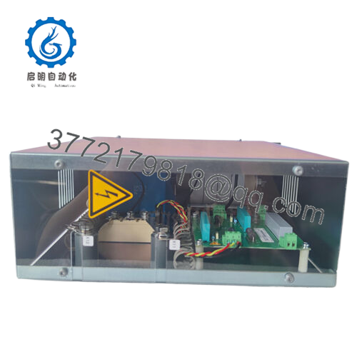
- Operation: Thyristor crowbar circuit triggers on overvoltage to clamp and dissipate energy
- Mounting: Typically DIN-rail or panel-mounted near field converter
- Dimensions (approximate): Compact enclosure (exact varies; consult ABB drawing for footprint)
- Weight: Approximately 1–2 kg
- Operating Temperature: -15 to +55 °C (typical for DCS800 accessories; derate if higher)
- Protection: Includes relay output for status signaling to drive control

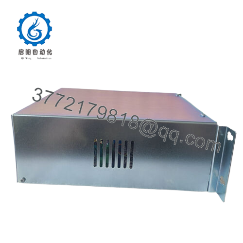
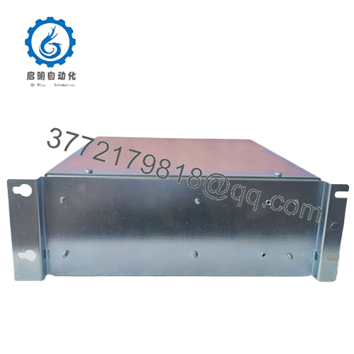
- DCF506-0140-51-0000000
Product Introduction
The ABB DCF506-0140-51-0000000 is an active overvoltage protection unit designed specifically for the field supply section of DCS800 DC drives. It clamps excessive voltages generated during field de-excitation or faults on inductive motor fields, preventing damage to thyristors in the field converter.
This module is mandatory for proper operation of 3-phase field exciters in DCS800-S01 and -S02 configurations rated up to 140 A. It provides reliable crowbar protection without adding significant latency, and plants retain it in legacy DCS800 systems to avoid field circuit failures during rapid de-fluxing or regen events.
Installation & Configuration Guide
Stage 1: Pre-Installation Preparation (5–10 minutes) ⚠️ Safety First: Shut down the drive and lock out/tag out all power sources (armature, field, control). Verify zero voltage on field terminals with multimeter. Wait 5 minutes for capacitors to discharge. Tools Required: ESD wrist strap, PH1/PH2 screwdriver, torque wrench, multimeter, wire labels, smartphone for photos. Data Backup: No software config on this passive module, but document existing field wiring diagram and any relay connections to drive I/O.
Stage 2: Removing the Old Module (5 minutes)
- Confirm power isolated.
- Label and disconnect field wiring (F+ / F- terminals) and any relay/status wires.
- Unscrew mounting hardware and remove unit straight from DIN rail or panel—avoid stressing connected cables.
- Inspect terminals for corrosion or loose strands. ⚠️ Note: Keep the old module for comparison until the new one is verified operational.
Stage 3: Installing the New Module (10 minutes)
- Ground yourself with ESD strap. Confirm replacement matches DCF506-0140-51-0000000 exactly.
- Configuration Clone (Crucial): No DIP switches or jumpers; unit is plug-and-play. Mount in same location/orientation as old.
- Connect field terminals to parallel across exciter output (positive to F+, negative to F-). Use same wire gauge and torque (typically 1.5–2.5 Nm).
- Wire relay output if used (for fault signaling to drive DI). Self-Checklist: [ ] Model matches, [ ] Connections secure and polarity correct, [ ] Mounting firm.
Stage 4: Power-On & Testing (10–15 minutes) Pre-Power Check: Multimeter verify no shorts across field terminals or to ground. Power-On Steps:
- Energize control power first, then field supply (keep armature isolated initially).
- Monitor drive panel for field-related faults; check relay status if wired.
- Ramp field current gradually; observe no unexpected trips.
- Run full drive test including field weakening/de-excitation cycles. ⚠️ Troubleshooting Note: Persistent overvoltage faults? Verify wiring polarity and exciter config. No protection trigger during de-flux test usually means correct installation; if crowbar fires unexpectedly, check for loose connections or mismatched rating.
Frequently Asked Questions (FAQ)
Is the DCF506-0140-51-0000000 hot-swappable? No. Power down the entire drive (armature and field) before swapping. Live work risks arc flash or false triggering the crowbar circuit.
Is this model obsolete, and is the stock genuinely new? DCF506 series remains supported for DCS800 spares as of 2026, though newer DCS880 may use different protection. Stock is new surplus from verified channels—traceable via ABB packing, anti-counterfeit inspection, and 24+ hour bench testing with simulated field load. Test reports available.
What is the direct replacement if this is out of stock? For 25–140 A range, check ABB for DCF506-0140-51 variants or consult DCS800 hardware manual for equivalents. In some cases, higher-rated DCF506-0520-51 serves if derated, but verify exact current/voltage match to avoid under-protection.
Will swapping this module affect drive programming or parameters? No—the DCF506 is hardware protection only; no firmware or parameters stored on it. Drive config (field exciter settings in DriveWindow) remains intact. Always power cycle and verify field monitor after install.
Why is the price lower than ABB direct? These are genuine new surplus from excess inventory or decommissioned systems—no refurb. Full QC including insulation resistance (>10 MΩ at 500 V), continuity, and functional crowbar simulation on DCS800 test setup. Backed by 1-year warranty.
Does this support redundancy or special applications? It’s single-unit protection; no built-in redundancy. For critical apps (e.g., marine), dual parallel units can add fault tolerance—check class rules. Works with standard DCS800 field setups; no special certs beyond ABB industrial ratings.


