
 WhatsApp: +86 16626708626
 Email:
  Phone: +86 16626708626
Description
3. Key Technical Specifications
| Parameter | Value |
|---|---|
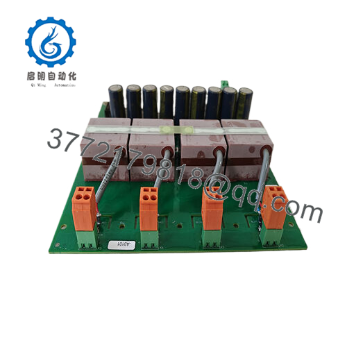
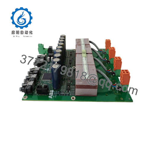
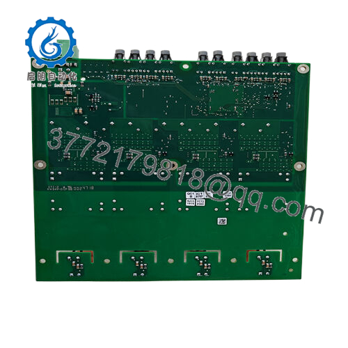
| Board Type | Drive Control / Crowbar Protection PCB |
| Application | Medium-voltage drives (ACS2000 systems) |
| Control Supply | 24 V DC (±10%) |
| Protection Function | Overvoltage suppression (crowbar circuit) |
| Switching Technology | IGCT-based power control |
| Max Voltage Handling | Up to ~4,500 V (system dependent) |
| Max Current | Up to ~600 A (application dependent) |
| Response Time | ≤10 ms control response |
| Isolation | Up to 2,500 V AC channel isolation |
| Operating Temperature | −40 to +70 °C |
| Storage Temperature | −40 to +85 °C |
| Mounting | Slot-mounted within drive cabinet |
| Protection Class | IP20 |
4. Product Introduction & Supply Chain Strategy
The ABB GDC801A 3BHE024747R0101 is a high-voltage drive control board used in ACS2000 medium-voltage drive systems. It manages switching logic and provides crowbar protection to safeguard power electronics during fault conditions such as overvoltage or regenerative energy spikes.
From a supply-chain standpoint, this board is a high-impact failure component in MV drives. Lead time variability is significant due to IGCT-based platform maturity and declining production volumes. Securing New Surplus inventory eliminates exposure to catastrophic drive downtime. Given the high replacement cost and long restart times of MV drives, maintaining buffer stock delivers strong ROI under a Total Cost of Ownership (TCO) model.

- GDC801A 3BHE024747R0101
5. Installation & Configuration Guide
Stage 1: Pre-Installation (Prep & Safety)
- Execute full lock-out/tag-out (LOTO) on MV drive and incoming feeders.
- Discharge DC bus capacitors completely—verify with meter.
- Use ESD protection; this PCB is sensitive to static discharge.
- Document wiring, connectors, and board slot position with photos.
Stage 2: Removal
- Remove retaining screws and release board locking mechanism.
- Extract the PCB straight out using guide rails—avoid flexing.
- Inspect backplane connectors for carbonization or pin damage.
Stage 3: Installation (Clone & Seat)
- Insert replacement board into the exact slot position.
- Ensure full seating into backplane connector—no partial engagement.
- Reconnect all control harnesses and grounding points.
- Verify shielding continuity for noise-sensitive circuits.
Stage 4: Power-On & Testing
- Re-energize control power first (24 V DC), then main drive supply.
- Monitor diagnostic LEDs and drive HMI for fault codes.
- Perform controlled startup—verify no crowbar trigger events.
- Validate switching response and drive stability under load.
6. Firmware/Software Versions & Upgrade Notes
- Recommended Practice: Maintain identical firmware and drive control parameters.
- Compatibility Risk: Firmware mismatch between control board and drive system can trigger false protection events or communication faults.
- Critical Warning:
- Upgrading firmware may alter protection thresholds and switching timing.
- Downgrading can disable compatibility with newer drive firmware or control layers.
- Always back up drive parameters and event logs before replacement to avoid extended commissioning delays.
7. Frequently Asked Questions (FAQ)
Q1: Is this unit truly new or surplus?
This product is a Brand New Surplus unit. It is not used, not refurbished, and not removed from a field installation. All PCB traces, connectors, and components are original with zero operational wear.
Q2: Why is this board critical to stock?
This is a drive protection and control board. Failure can trip the entire MV drive, leading to production shutdown. Replacement lead times are unpredictable, making buffer stock essential.
Q3: Is this part approaching obsolescence?
Yes. IGCT-based drive platforms are mature. Availability is tightening, and last-time-buy planning is strongly advised.
Q4: Can this board be repaired instead of replaced?
Field repair is not recommended. High-voltage stress degrades components in ways that are not visible. Replacement with New Surplus ensures predictable reliability.
Q5: Can I hot-swap this module?
No. Full shutdown and DC bus discharge are mandatory. Hot-swapping risks severe equipment damage and safety hazards.
Q6: What stocking strategy do you recommend?
- Critical drives: 1 unit onsite (minimum insurance spare)
- Multi-drive plants: 1–2 shared units across similar systems
- Consider vendor consolidation to secure consistent sourcing
Q7: What is the expected lifecycle?
New Surplus units typically support 10–15 years of operation under proper thermal and electrical conditions, aligning with long MV drive service intervals and minimizing lifecycle replacement frequency.


