
 WhatsApp: +86 16626708626
 Email:
  Phone: +86 16626708626
Description
2. Product Core Brief
- Model: IPSYS01
- Brand: ABB
- Series: ABB Bailey / Harmony Rack I/O Power System
- Core Function: Provides regulated DC power for DCS modules
- Product Type: System Power Module / Power Supply
- Key Specs: 102–264 VAC input, multi-rail DC output, 260 W max output
- Condition: New Original (New Surplus)
3. Key Technical Specifications
| Parameter | Value |
|---|---|
| Model | IPSYS01 |
| Manufacturer | ABB |
| Product Type | System Power Module |
| System Compatibility | ABB Bailey / Harmony Rack I/O |
| Input Voltage | 102–264 VAC or 102–144 VDC |
| Full Load Input Current | 4.3 A (120 VAC), 2.0 A (240 VAC), 4.3 A (125 VDC) |
| Output Voltages | 5 VDC, +15 VDC, −15 VDC, 25.5 VDC |
| Maximum Output Power | 260 W total |
| Hold-Up Time | ~20 ms after power loss |
| Line Regulation | ±0.5% of nominal output |
| Cooling | Natural convection |
| Heat Dissipation | ~175 W |
| Dimensions | 44.45 × 4.83 × 21.84 cm |
| Weight | ~2.5 kg |
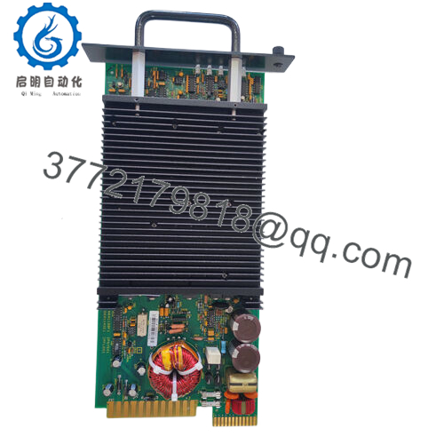
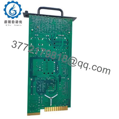
The module converts plant AC/DC supply into regulated multi-rail DC voltages used by Harmony system modules and I/O racks.
4. Product Introduction
The ABB IPSYS01 is a system power supply module used in ABB Bailey / Harmony Rack I/O distributed control systems. It converts incoming AC or DC plant power into several regulated DC rails required by Harmony controllers and I/O modules.
In actual plant installations, IPSYS01 modules sit inside the Harmony Modular Power System II chassis and feed multiple rack modules simultaneously. The design supports load sharing between parallel power modules, allowing redundant power configurations for high-availability DCS cabinets.
5. Installation & Configuration Guide
Stage 1: Pre-Installation Preparation (10 minutes)
⚠️ Safety First
- Notify operations and schedule the cabinet shutdown.
- Bring the process to a safe state.
- Apply lockout/tagout (LOTO) to the cabinet mains supply.
- Wait at least 5 minutes for power supply capacitors to discharge.
Tools Required
- ESD wrist strap
- PH1 screwdriver
- Multimeter (Fluke 115 recommended)
- Wire labels
- Smartphone for wiring documentation
Data Backup
Power modules do not store logic, but you should still:
- Document cabinet power wiring.
- Photograph the existing module and chassis connections.
- Record redundancy configuration if multiple supplies are installed.
Stage 2: Removing the Old Module (5–10 minutes)
- Open the cabinet and locate the Harmony Modular Power System chassis.
- Identify the IPSYS01 module.
- Label AC/DC input wires and grounding points.
- Disconnect input power wiring.
- Release the module retaining screws or latches.
- Pull the module straight out of the chassis slot.
⚠️ Inspect the backplane connector and airflow path for dust or heat damage.
Stage 3: Installing the New Module (10 minutes)
- Wear an ESD wrist strap before handling the new module.
- Verify the replacement unit IPSYS01 matches the removed hardware.
Configuration Check
- If the cabinet uses parallel redundant power supplies, confirm:
- Load sharing configuration
- Correct chassis slot location
- Insert the module into the chassis until the connector seats fully.
- Tighten the retention screws.
- Reconnect the AC or DC input supply and ground.
Self-Checklist
- Model number verified
- Power wiring correct
- Ground connection secure
- Module fully seated in chassis

- IPSYS01
Stage 4: Power-On & Testing (10–15 minutes)
Pre-Power Check
- Use a multimeter to confirm no short between input phases and ground.
Startup Procedure
- Restore cabinet power.
- Verify the power module status indicators.
- Measure output rails if test points are available.
Typical expected rails:
- ~5.1 VDC logic supply
- +15 VDC analog supply
- −15 VDC analog supply
- ~25.5 VDC field supply
- Confirm that connected Harmony I/O modules boot normally.
⚠️ Troubleshooting Tip
If the rack fails to start:
- Check load sharing wiring when multiple supplies are installed.
- Verify that the total load does not exceed 260 W per module.
- Inspect the chassis power monitor module (IPMON series) for alarms.
6. Frequently Asked Questions (FAQ)
Q1: Can the ABB IPSYS01 be hot-swapped?
No. In most Harmony installations this module is not hot-swappable. Removing it under load can collapse the DC rails and shut down the entire rack.
Q2: What systems use the IPSYS01?
It is commonly used in:
- ABB Bailey INFI-90 / Harmony DCS systems
- Harmony Rack I/O cabinets
- Modular Power System II chassis
These platforms are still common in power generation and large process plants.
Q3: Can multiple IPSYS01 modules run in parallel?
Yes. The design supports current sharing between modules within about 5% at full load, allowing redundant configurations for improved uptime.
Q4: What usually causes power module failures?
In the field, the typical failure modes are:
- Thermal stress from clogged cabinet airflow.
- Overloaded racks exceeding the 260 W limit.
- Aging electrolytic capacitors after 15–20 years of operation.
Power supplies are often the first component to fail in older DCS racks.
Q5: If this module fails, will the control program be lost?
No. The IPSYS01 only provides power. The control logic resides in the controller CPU modules. However, a power failure will stop the entire rack until power is restored.
Q6: Why are these still sold as surplus instead of new from ABB?
Most Harmony / Bailey platforms are mature or legacy systems. OEM factories focus on newer architectures like AC800M and System 800xA, so many spare parts today come from industrial surplus inventory or refurbishment channels.


