
 WhatsApp: +86 16626708626
 Email:
  Phone: +86 16626708626
Description
Key Technical Specifications
| Parameter | Value |
|---|---|
| Brand | ABB |
| Model | KSD211B101 (KS D211 B101), 3BHE022455R1101 |
| Product type | Input Coupling Unit (ICU) |
| System / range | UNITROL® 6000 excitation / industrial control interface |
| Function | Input coupling, isolation, and conditioning of field signals |
| Power supply | 24 V DC |
| Input voltage range | 0–10 V DC |
| Input current range | 4–20 mA |
| Number of channels | 16 inputs, 16 outputs (per vendor spec) |
| Response time | < 10 ms |
| Protection class | IP20 |
| Mounting | DIN rail compatible |
| Approx. dimensions | 160 mm × 60 mm × 90 mm (L × W × H) |
| Net weight | ≈ 0.46–0.50 kg |
| Country of origin | Sweden / Switzerland / Germany (varies by listing) |
| Customs / HS code | 8537101190 or 85437000 (industrial control apparatus) |
4. Product Introduction
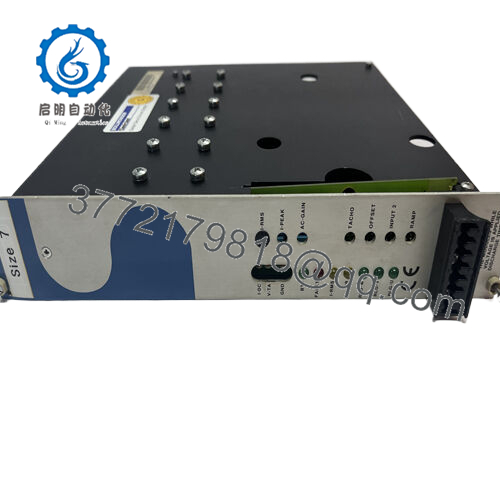
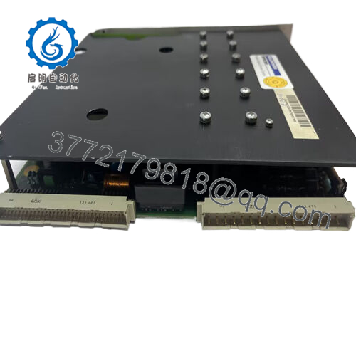
The ABB KSD211B101 (KS D211 B101), part number 3BHE022455R1101, is an input coupling unit used to bring analog field signals—typically 0–10 V and 4–20 mA—into UNITROL 6000 excitation systems and related industrial control applications. It provides signal conditioning, galvanic isolation, and a DIN‑rail form factor, which makes it easy to integrate into crowded control cabinets.
You reach for this module when you need a clean, OEM‑approved interface between field transmitters and the excitation or DCS layer, rather than a patchwork of third‑party isolators. The 24 V DC supply, fast response (< 10 ms), and multi‑channel layout keep wiring compact while still meeting typical protection and control timing requirements.
5. Troubleshooting Quick Reference
Use this to decide if the KSD211B101 ICU is actually bad, or if the problem is wiring, the field device, or the controller.
| Symptom | Possible Cause | Relevance to this Part | Quick Check Method | Recommendation |
|---|---|---|---|---|
| No input signals seen by controller | No 24 V DC to ICU, loose terminal, blown upstream fuse | ✅ High | Measure 24 V DC at ICU supply terminals; tug‑test supply and signal wiring | Restore DC supply and tighten terminals; if supply is good and all channels read zero, suspect the ICU. |
| One channel reads 0 while others are OK | Open field loop, broken pair, single channel damage | ⚠️ Medium | Measure loop current at terminals for that channel with a meter in series | Fix field loop first; if loop current is correct but ICU output stays dead, that channel is likely bad. |
| All channels offset or noisy | Shared grounding issue, shield terminations, 24 V noise | ⚠️ Medium | Check shield bonding, compare ICU input vs. raw transmitter output with a meter | Clean up grounding and 24 V supply; replace the ICU only if noise follows the module to a test setup. |
| Slow response to process changes | Heavy input filtering or ICU fault | ⚠️ Medium | Step the field signal (simulator or calibrator) and time the response at ICU out | If response is far slower than < 10 ms class and wiring is fine, plan ICU replacement. |
| ICU runs warm or smells “hot” | Overload, wrong supply voltage, internal failure | ✅ High | Verify supply is 24 V DC, check for discoloration or burn marks on housing | Remove from service immediately if overheating; do not keep it in a protection path. |
| Controller input OK on direct injection | Problem vanishes when bypassing ICU | ✅ High | Inject 4–20 mA or 0–10 V directly into controller channel, bypassing ICU | If controller behaves normally without the ICU, tag and replace the ICU. |
If you get stuck, take photos of the ICU wiring, note channel numbers, record a quick table of field vs. ICU vs. controller readings, and send that to your excitation or DCS specialist before you start swapping multiple modules.

- KSD211B101
6. Frequently Asked Questions (FAQ)
Q1: What does the ABB KSD211B101 / 3BHE022455R1101 actually do in the system?
It is an input coupling unit that conditions, isolates, and routes multiple analog signals (typically 0–10 V and 4–20 mA) from field transmitters into UNITROL 6000 excitation systems or related industrial controls. In practice, it sits between the field and the controller, acting as a multi‑channel isolator and interface.
Q2: Is KSD211B101 a direct replacement for any KS D211 B input module?
You need to match both the KS D211 B101 designation and the ABB part number 3BHE022455R1101; other KS D211 variants may differ in channel count, rating, or internal configuration. Always cross‑check the part number on the existing module and the original excitation or DCS parts list before treating it as a one‑for‑one swap.
Q3: What input signal types can this ICU handle?
The published specs show support for a 0–10 V DC input range and 4–20 mA analog current inputs, intended for typical process transmitters. If you have anything outside those ranges, verify with the ABB datasheet or use external conditioning; do not assume it will tolerate unusual signal levels.
Q4: What supply voltage does the KSD211B101 require?
It runs from a 24 V DC control supply, which must be within the limits given by ABB and properly protected by fuses or breakers. Before blaming the ICU for dead channels, check that the 24 V rail is stable and within tolerance under load.
Q5: Can I mount this module directly on a backplane, or is it DIN‑rail only?
Available technical data and vendor specs call out DIN‑rail compatible mounting with a compact enclosure size. In most retrofits it drops into the existing DIN rail next to other UNITROL or I/O modules; forcing it onto a non‑standard mounting is a good way to stress terminals and cause intermittent faults.
Q6: Is the KSD211B101 still active, or is it effectively a legacy part?
It is tied to UNITROL 6000 and similar systems, which are still heavily used but not exactly new builds, so in the field this module behaves like a specialized legacy component with limited stock. That is why many plants keep at least one spare ICU per critical excitation system on the shelf.
Q7: Why do different listings show slightly different weights, dimensions, or HS codes?
Vendors pull data from various ABB logistics and customs sources, so you see minor discrepancies—0.46 vs. 0.5 kg, or HS 8537101190 vs. 85437000. For engineering and panel layout, trust the ABB mechanical drawing; treat the logistics numbers as shipping info, not precise design data.


