
 WhatsApp: +86 16626708626
 Email:
  Phone: +86 16626708626
Description
2. Product Core Brief
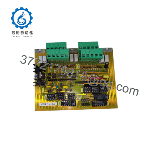
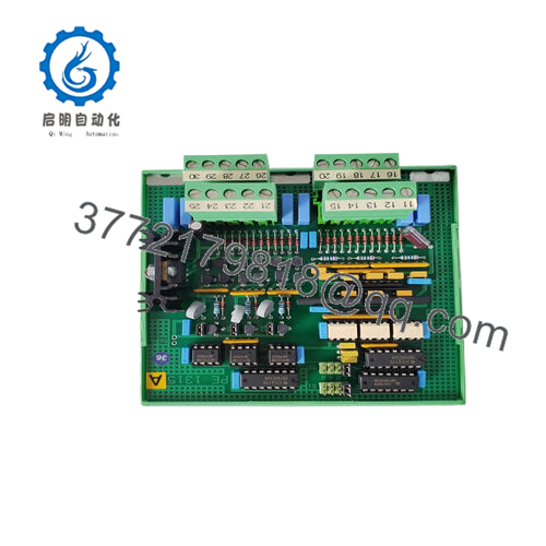
- Model: PE1315A (5FSE707630-7)
- Brand: ABB
- Series: ABB industrial signal interface modules
- Core Function: Pulse signal isolation and amplification
- Product Type: Opto-isolated pulse amplifier module
- Key Specs: 3 signal channels; 5–24 V DC input/output; 2500 V isolation
- Condition: New Original / New Surplus
3. Key Technical Specifications
| Parameter | Value |
|---|---|
| Manufacturer | ABB |
| Model | PE1315A |
| Part Number | 5FSE707630-7 |
| Product Type | Opto-isolated pulse amplifier |
| Input Voltage Range | 5–24 V DC |
| Output Voltage Range | 5–24 V DC |
| Output Current | Up to ~13 mA (configurable limit) |
| Isolation Voltage | 2500 V optical isolation |
| Channels | 3 channels (A, B, Strobe) |
| Response Time | Rise/Fall < 10 µs |
| Operating Temperature | −20 °C to +70 °C |
| Storage Temperature | −40 °C to +80 °C |
| Mounting | DIN rail / panel installation |
| Weight | Approx. 0.24 kg |
Optical isolation separates input signals from output circuits, preventing ground loops and protecting control electronics from transient voltage events.
4. Product Introduction
The ABB PE1315A (5FSE707630-7) is an opto-isolated pulse amplifier used in industrial control systems to isolate and condition high-speed pulse signals. The module converts and amplifies pulse inputs while electrically isolating the field signal from the control electronics.
In practical installations, this device is typically used between sensors (encoders, pulse generators, speed probes) and higher-level controllers or measurement equipment. The optical isolation stage protects the control system from noise, voltage spikes, and ground loop errors while maintaining fast signal response in the microsecond range.

- PE1315A 5FSE707630-7
5. Installation & Configuration Guide
Estimated time for a trained controls technician: 20–30 minutes
Stage 1 — Pre-Installation Preparation (5–10 minutes)
⚠️ Safety First
- Inform operations of the maintenance activity.
- Place the process equipment in a safe condition.
- Perform lockout/tagout (LOTO) on the control cabinet power supply.
- Wait 5 minutes for internal power rails to discharge.
Tools Required
- ESD wrist strap
- PH1 screwdriver
- Multimeter (Fluke 115 or equivalent)
- Wire labels
- Smartphone for documentation
Data Backup
Before touching the wiring:
- Record the signal source (encoder, pulse generator, sensor)
- Document terminal wiring numbers
- Photograph the existing terminal layout
Pulse wiring mistakes are a common cause of commissioning delays.
Stage 2 — Removing the Old Module (5 minutes)
- Open the control cabinet and locate the PE1315A module.
- Label each input and output terminal wire.
- Disconnect signal wiring carefully.
- Release DIN-rail or mounting screws.
- Remove the module.
⚠️ Important
Do not discard the old unit yet. Keep it nearby until the replacement passes testing.
Stage 3 — Installing the New Module (5–10 minutes)
- Attach the ESD wrist strap before handling the electronics.
- Confirm the replacement model PE1315A / 5FSE707630-7 matches exactly.
- Mount the module onto the DIN rail or panel bracket.
- Reconnect wiring according to the documentation photos.
- Verify grounding and shielding connections.
Self-Checklist
- Model verified
- Signal wiring correct
- Shield grounding correct
- Module secured to DIN rail
Stage 4 — Power-On & Signal Testing (10 minutes)
Pre-Power Checks
- Verify 24 V control power polarity
- Confirm no short between signal lines and ground
Startup Procedure
- Restore cabinet power.
- Confirm module power indicator (if present).
- Inject a test pulse from the signal source.
- Measure output using an oscilloscope or counter.
- Confirm output matches expected signal level.
⚠️ Troubleshooting Note
If the output signal is missing:
- Check channel selection (A / B / Strobe)
- Verify encoder or pulse generator output level
- Confirm proper grounding of shielded cable
Technical Pitfalls & Survival Guide
Real problems encountered during field replacements.
❗ Firmware / Controller Interpretation Issues
Some PLC or DCS input cards expect specific signal timing.
If the amplifier slightly changes pulse width or edge timing, the receiving controller might miscount pulses.
I once saw a turbine speed measurement loop read half the actual RPM because the pulse conditioning stage inverted the signal.
Always confirm signal polarity and edge detection settings in the PLC.
❗ Wiring Channel Confusion
Three channels (A, B, Strobe) means technicians sometimes mix them.
Take a clear photo before removal. Encoder wiring mistakes are one of the most common commissioning errors.
❗ Ground Loop Problems
Isolation amplifiers solve ground loop issues — but only if used correctly.
If someone bonds the shield at both ends, you reintroduce the problem the isolation stage was supposed to fix.
❗ Power Supply Noise
Pulse amplifiers are sensitive to noisy 24 V rails.
In cabinets with large drives or contactors, install a dedicated filtered supply if signal jitter appears.
❗ Electrostatic Discharge (ESD)
Isolation boards include sensitive optocouplers.
Static discharge during installation can silently damage them.
I once saw a module fail during commissioning after being handled without an ESD strap. The optocoupler degraded and produced intermittent pulses.
Follow these checks and you’ll avoid most troubleshooting loops during signal conditioning module replacement.
6. Frequently Asked Questions (FAQ)
Q1: Can the PE1315A be hot-swapped?
No. This device is not designed for hot swapping. Removing it under power can damage signal interfaces or the connected controller.
Shut down cabinet power first.
Q2: What does this module actually do in a control system?
It isolates and amplifies pulse signals from sensors like:
- incremental encoders
- speed probes
- pulse generators
- tachometer outputs
The optical isolation protects the control system from electrical noise and ground potential differences.
Q3: Is the PE1315A obsolete?
Many installations still operate with this module, but availability today usually comes from surplus spare-parts inventory rather than new production.
Lead times depend on stock availability.
Q4: Can this module interface directly with PLC high-speed inputs?
Yes, as long as:
- signal voltage matches the PLC input range
- pulse frequency stays within the input card specification
Always check the PLC input threshold and timing requirements.
Q5: Why are surplus units cheaper than ordering from ABB?
OEM spare parts pricing includes:
- long-term lifecycle support
- certified logistics channels
- guaranteed availability
Surplus units come from project overstock or spare inventory, which reduces price but still provides genuine hardware.


