
 WhatsApp: +86 16626708626
 Email:
  Phone: +86 16626708626
Description
Product Core Brief
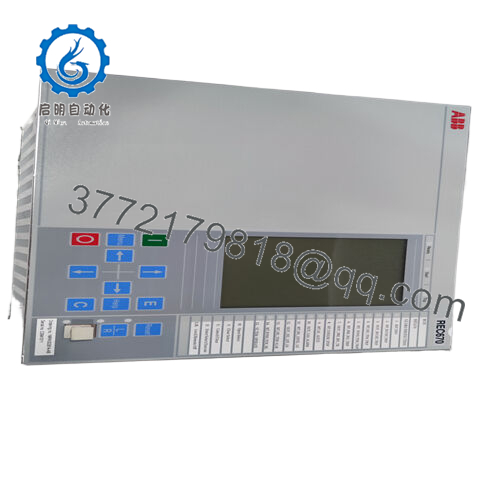
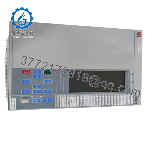
- Model: REB670
- Brand: ABB (Hitachi Energy)
- Series: Relion® 670
- Core Function: Busbar differential protection
- Product Type: IED (Intelligent Electronic Device) / Protection Relay
- Key Specs: Up to 6 zones, single/double/triple busbar support, IEC 61850 compliant, high I/O capacity
- Condition: New Original / Factory Configured (availability varies; check lead time)
Key Technical Specifications
- Application Voltage Levels: Medium to extra-high voltage (MV to EHV)
- Protected Configurations: Single, double, triple busbar; with/without transfer bus; double-breaker; one-and-a-half breaker
- Protection Zones: Up to 6 differential zones
- Current Inputs (Ir): Rated 1 A or 5 A; operative range 0.2–40 × Ir
- Overload Capability: Continuous 4 × Ir; 1-second 100 × Ir
- AC Voltage Inputs (Ur): Rated 110 V; operative range 0.5–288 V; continuous overload 420 V
- Auxiliary Power Supply: Typically 24–60 V or 90–250 V DC/AC (configuration-dependent)
- Communication Protocols: IEC 61850 (including 9-2LE process bus in later versions), DNP3, IEC 60870-5-103/104
- Operating Temperature: −25 to +55 °C (standard; extended options available)
- Mounting: Panel or rack (19″ rack compatible in 670 series)
- I/O Capability: Extensive binary/analog I/O (varies by config; up to dozens of contacts)
- Standards Compliance: IEC 61850, IEEE C37.234 (busbar protection guide)
Always cross-check the exact ordering code (e.g., REB670*1.x-…) against the Hitachi Energy datasheet for your firmware and hardware variant — I/O count and features change with configuration.

- REB670
Product Introduction
The ABB REB670 is a high-end busbar protection relay from the Relion 670 series, built as an IED for fast, selective differential protection of busbars, T-connections, and meshed corners in substations from medium to extra-high voltage. It covers complex arrangements like double or triple bus with transfer, providing reliable internal fault tripping while staying secure during external faults or CT saturation.
Field teams select the REB670 for its zone scalability (up to six), integrated sensitive and backup differential algorithms, and IEC 61850 interoperability. It delivers sub-cycle operate times on internal faults, CT supervision to block on open/short conditions, and extensive supervision to minimize false trips — critical in high-energy bus systems where a misoperation can cascade widely.
Installation & Configuration Guide
Stage 1: Pre-Installation Preparation (15–30 minutes) ⚠️ Safety First: Coordinate with operations for bus outage. Verify breaker open and bus de-energized. Lock out/tag out all sources feeding the bus section. Wait 10+ minutes for stored energy discharge; confirm zero voltage on terminals with multimeter. Tools Required: Grounded ESD wrist strap, torque screwdriver (PH1/PH2), digital multimeter, wire labels/markers, camera/smartphone for photos, PCM600 software laptop with Ethernet cable. Data Backup: Use PCM600 to read and export full IED configuration, parameters, disturbance records, and firmware version. Photograph all rear terminal wiring, LED indications, and any DIP/link settings (rare on 670 series but check).
Stage 2: Removing the Old Module (10–20 minutes)
- Open the panel door and locate the REB670 IED in its rack or panel cutout.
- Label every wire and fiber connection meticulously — note slot positions. Disconnect CT/VT circuits first (short CT secondaries if live elsewhere), then binary I/O, comms, and power.
- Power down auxiliary supply. Release mounting screws/clamps and slide the IED out straight — watch for fragile rear connector pins.
- Inspect rack slot for dust, corrosion, or damaged backplane contacts; clean if required. ⚠️ Note: Retain the old IED intact for side-by-side comparison during commissioning — firmware or config mismatches cause most post-swap headaches.
Stage 3: Installing the New Module (15–25 minutes)
- Apply ESD strap. Verify replacement ordering code matches exactly (REB670 variant, including hardware options like analog input count).
- Configuration Clone (Crucial): Load exported .pcm file via PCM600 before insertion if possible, or prepare to download post-power-up. Match any site-specific settings (CT ratios, zone assignments, trip logic).
- Slide IED into rack until fully seated (firm push; listen for connector engagement). Secure screws to spec torque (typically 2–3 Nm).
- Reconnect all terminals exactly per labels — use torque screwdriver on CT/VT screws to avoid loose connections. Self-Checklist: [ ] Ordering code matches, [ ] Config file loaded/verified, [ ] Wiring torqued and labeled, [ ] All modules seated and locked.
Stage 4: Power-On & Testing (30–60 minutes) Pre-Power Check: Measure insulation resistance (>100 MΩ at 500 V) on CT circuits; verify no shorts on aux power (24/48/110/220 V range). Power-On Steps:
- Apply auxiliary power only (no CT/VT energized initially).
- Observe front LEDs: Power green, Ready green, others off = normal; red Alarm/ERR = halt and check events.
- Connect PCM600 via Ethernet; read IED — confirm firmware version matches original (mismatch triggers “Parameter Error” or comms block).
- Download saved configuration; perform consistency check and parameter compare.
- Energize CT/VT circuits gradually; monitor differential currents (should be near zero on healthy bus). Test trip inhibit, open-CT block, and zone supervision. Simulate faults via injection if possible. ⚠️ Troubleshooting Note: Persistent Alarm LED or “Diff Blocked” often means CT circuit open, wrong polarity, or firmware mismatch — re-verify wiring photos and reload config. No GOOSE/61850 comms? Check Ethernet ports and substation clock sync.
These steps keep most replacements under two hours of actual downtime.
Frequently Asked Questions (FAQ)
Can the REB670 be hot-swapped or replaced live? No. Never insert or remove under power. The IED connects directly to live CT circuits — pulling it live risks open-CT conditions that could trip adjacent protection or damage inputs. Isolate aux power and short CT secondaries first.
Is the REB670 obsolete in 2026? No, it’s still active in the Hitachi Energy Relion portfolio with ongoing support, firmware updates (up to 2.2.x), and new unit availability (lead times 6–10 weeks typical). Some older configs may be harder to source exact matches, but it’s not discontinued.
What is the direct replacement if a specific REB670 variant is unavailable? No one-for-one drop-in exists due to custom ordering codes, but later Relion 670 series (same hardware platform) or REB670 with updated firmware often works. For new projects, check Hitachi Energy for successors like enhanced 670 series or 650 series variants. Provide your full ordering code for exact cross-reference.
Will swapping the REB670 erase my protection settings or logic? No, if you export via PCM600 first — all parameters, zone definitions, and custom logic store in non-volatile memory. But always back up before removal. I’ve seen rushed swaps lose custom GOOSE mappings, forcing full re-engineering on-site.
Why buy surplus/new surplus when OEM is available? OEM direct often has longer lead times and higher cost for custom configs. Surplus units (new/unused from canceled projects or spares) go through full functional testing in a 670-series rack simulation, including power-up, comms, I/O checks, and 24-hour burn-in. We provide test reports; backed by our warranty, not ABB’s full factory one.
How do you test REB670 units before shipping? We install in a Relion 670 test rack, apply aux power, connect simulated CT currents (via Omicron or similar), verify differential operate/restrain, open-CT block, zone supervision, and LED/events. Insulation tested at 500 V (>100 MΩ), firmware read/documented. Videos/photos available on request — no shortcuts like power-on only.
Pay attention to these details and you’ll avoid the usual substation headaches.


