
 WhatsApp: +86 16626708626
 Email:
  Phone: +86 16626708626
Description
2. Product Core Brief
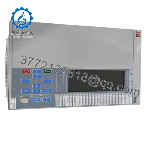
- Model: REC650 (1MRK008514-AA)
- Brand: ABB
- Series: ABB Relion® 650 Series
- Core Function: Feeder protection and bay control
- Product Type: Numerical Protection & Control Relay (IED)
- Key Specs: IEC 61850 communication, <20 ms trip time, configurable protection logic
- Condition: New Original / New Surplus
3. Key Technical Specifications
| Parameter | Value |
|---|---|
| Manufacturer | ABB |
| Model | REC650 |
| Order Code | 1MRK008514-AA |
| Product Type | Numerical Protection & Control Relay (IED) |
| Series | Relion® 650 |
| Typical Application | Feeder, transformer, capacitor bank protection |
| Rated Current Inputs | 1 A or 5 A CT inputs |
| Voltage Inputs | Standard VT inputs (≈100–220 V measurement) |
| Power Supply | 24–250 V DC / 100–240 V AC |
| Power Consumption | ≤30 W typical |
| Communication Protocols | IEC 61850 (GOOSE, MMS, SV), Modbus RTU/TCP, DNP3, IEC 60870-5-103 |
| Ethernet Ports | Typically 2 × Ethernet |
| Digital Inputs / Outputs | Configurable binary I/O depending on configuration |
| Fault Recording | Oscillography and event records with sub-millisecond resolution |
| Operating Temperature | −40 °C to +70 °C |
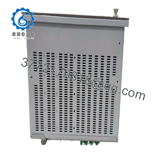
| Mounting | Panel or 19-inch rack mounting |
| Weight | ~2.8–3.5 kg depending on configuration |
The REC650 platform records fault events and oscillography for post-fault analysis and supports IEC-61850 digital substation communication using GOOSE and MMS messaging.
4. Product Introduction
The ABB REC650 1MRK008514-AA is a multifunction numerical protection and control relay from the ABB Relion® 650 series. It serves as an Intelligent Electronic Device (IED) for medium- and high-voltage distribution systems, providing feeder protection, control logic, measurement, and event recording in a single device.
Utilities and large industrial substations deploy REC650 relays as bay controllers or feeder protection units. The platform supports IEC 61850 digital substations, including GOOSE messaging for high-speed interlocking and trip signaling across protection devices.
5. Installation & Configuration Guide
Stage 1 — Pre-Installation Preparation (Estimated time: 10 minutes)
⚠️ Safety First
- Notify operations and place the feeder or bay under maintenance control.
- Trip and isolate the circuit breaker.
- Apply lock-out/tag-out (LOTO) to all control power sources.
- Verify VT and CT circuits are safely isolated before removing wiring.
Tools Required
- ESD wrist strap
- Small terminal screwdriver
- Multimeter (Fluke 115 or equivalent)
- Laptop with ABB PCM600 engineering software
- Smartphone for documentation
Data Backup
Before removing the old relay:
- Export the IED configuration (CID/SCD files) from PCM600.
- Save event logs and disturbance records.
- Photograph terminal blocks and CT/VT wiring.
If you skip this step, recreating protection logic later becomes painful.
Stage 2 — Removing the Old Relay (Estimated time: 5–10 minutes)
- Open the relay panel and remove the front mounting screws.
- Label all wiring:
- CT circuits
- VT circuits
- Binary inputs/outputs
- Communication cables
- Disconnect terminal blocks carefully.
⚠️ Important:
Short CT circuits before removal if the design requires it. Open CT circuits under load can generate dangerous voltages.
- Slide the relay out of the panel or rack frame.
- Inspect the panel wiring and connectors for loosened terminals.
Stage 3 — Installing the New Relay (Estimated time: 10 minutes)
- Wear an ESD strap before handling the device.
- Verify the exact order code:
- REC650
- 1MRK008514-AA
Different suffixes often mean different I/O hardware configurations.
- Insert the relay into the panel cutout or 19-inch rack adapter.
- Reconnect wiring according to your photos and drawings.
Key wiring checks:
- CT polarity (S1/S2 orientation)
- VT phase mapping
- Binary trip outputs to breaker coil
Self-Checklist
- CT polarity correct
- VT phases correct
- Communication Ethernet connected
- Relay securely mounted
Stage 4 — Power-On & Testing (Estimated time: 10–15 minutes)
Pre-Power Check
- Measure auxiliary supply voltage (usually 110 V DC or 220 V AC).
- Verify no short between supply and chassis ground.
Power-On Procedure
- Apply auxiliary control power.
- Confirm the relay boots normally and HMI display activates.
- Connect the engineering laptop using ABB PCM600.
- Download the saved configuration file to the relay.
- Verify communication over IEC 61850 or Modbus.
Functional checks:
- Binary input test
- Trip output simulation
- Time synchronization (IRIG-B / SNTP)
⚠️ Troubleshooting Tip
If IEC 61850 communication fails:
- Verify IP address and subnet.
- Confirm the SCD file matches the station configuration.
- Check that GOOSE VLAN settings match the substation switch configuration.

- REC650 1MRK008514-AA
6. Frequently Asked Questions (FAQ)
Q1: Can the REC650 be hot-swapped?
No.
Protection relays like this are not hot-swappable devices. Removing it under power can interrupt CT circuits and cause dangerous voltages. Always isolate the protection panel first.
Q2: Is the REC650 still supported by ABB?
Yes.
The Relion 650 series remains widely used in substations and industrial grids. Firmware updates and engineering tools such as PCM600 are still available through ABB support channels.
Q3: What engineering software programs this relay?
ABB uses PCM600 with the Connectivity Package for REC650.
This software handles:
- Protection function configuration
- IEC 61850 engineering
- Disturbance record retrieval
Q4: Will replacing the relay erase my protection settings?
Yes, if you don’t back them up.
Protection settings are stored inside the IED. If the old relay fails completely, you’ll need the PCM600 project file or CID export to restore configuration.
Q5: Why do some REC650 units have different suffixes (AA, AB, CB)?
Those suffixes define:
- I/O hardware configuration
- Installed protection functions
- Communication modules
Two relays with different suffixes may not be direct drop-in replacements.
Always match the full order code, not just “REC650”.
Q6: How are these relays tested before shipment?
Our standard verification process includes:
Inbound inspection
- Serial number validation
- Visual inspection for connector damage
Electrical testing
- Insulation test with 500 V Megger (>100 MΩ)
- Ground continuity verification
Functional testing
- Powered on a test protection rack
- Binary I/O simulation
- Ethernet communication verification
Burn-in
- Continuous power-on test for 24 hours
After testing:
- Relay sealed in ESD packaging
- Foam protection + heavy-duty carton
- QC label with inspection date
Test photos or videos can be provided if required.


