
 WhatsApp: +86 16626708626
 Email:
  Phone: +86 16626708626
Description
2. Product Core Brief
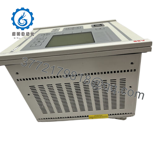
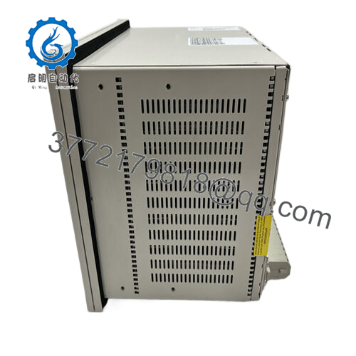
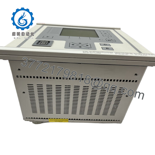
- Model: REF545KB133AAAA
- Brand: ABB
- Series: ABB REF54x Feeder Terminal Series
- Core Function: Medium-voltage feeder protection and control
- Product Type: Numerical Protection Relay / Feeder Terminal
- Key Specs: 1 A / 5 A CT inputs, multiple protection functions, SCADA communication interfaces
- Condition: New Original / New Surplus
3. Key Technical Specifications
| Parameter | Value |
|---|---|
| Manufacturer | ABB |
| Model | REF545KB133AAAA |
| Product Type | Feeder Protection and Control Relay |
| Typical Application | Medium-voltage distribution feeder protection |
| Current Inputs | 1 A or 5 A CT inputs |
| Auxiliary Power Supply | 100–240 V AC or DC |
| Protection Functions | 50/51 overcurrent, 50N/51N earth fault, 49 thermal overload, 79 auto-reclosing |
| Communication Protocols | IEC 60870-5-103, Modbus RTU, SPA/LON bus (depending on configuration) |
| Measurement Functions | Current, voltage, power, frequency, power factor |
| Binary Inputs / Outputs | Configurable digital I/O for breaker control |
| Event Recording | Fault and disturbance recording |
| Operating Temperature | −25 °C to +70 °C |
| Compliance | IEC 60255 protection relay standards |
The REF545 platform integrates protection, control, measurement, and monitoring functions for medium-voltage distribution networks and industrial switchgear systems.
4. Product Introduction
The ABB REF545KB133AAAA is a multifunction feeder protection relay designed for medium-voltage distribution systems such as industrial substations, utility feeders, and motor feeders. The device integrates protection, measurement, control logic, and communication interfaces within a single Intelligent Electronic Device (IED).
In practical deployments, REF545 units serve as feeder terminals in switchgear panels, performing overcurrent protection, earth-fault detection, breaker control, and disturbance recording. The platform communicates with SCADA or substation automation systems using standard protocols such as IEC 60870-5-103 or Modbus, enabling centralized monitoring and control.
5. Installation & Configuration Guide
Stage 1 — Pre-Installation Preparation (Estimated time: 10 minutes)
⚠️ Safety First
- Inform operations and place the feeder under maintenance control.
- Open the breaker and isolate the feeder.
- Apply lock-out/tag-out (LOTO) to auxiliary control power.
- Confirm CT and VT circuits are safely isolated.
Tools Required
- ESD wrist strap
- Small terminal screwdriver
- Digital multimeter (Fluke 115 or equivalent)
- Laptop with ABB protection configuration software
- Smartphone for documentation
Data Backup
Before removing the relay:
- Export the relay configuration and protection settings.
- Record communication address and protocol settings.
- Photograph terminal blocks and CT/VT wiring.
This step prevents hours of reconfiguration later.
Stage 2 — Removing the Old Relay (Estimated time: 5–10 minutes)
- Remove the front mounting screws on the switchgear panel.
- Label wiring:
- CT circuits
- VT circuits
- Binary I/O
- Communication cables
- Disconnect terminal blocks carefully.
⚠️ Important
CT circuits may require shorting links before removal. An open CT secondary can produce dangerous voltages.
- Slide the relay out of the panel frame.
- Inspect wiring terminals for loose connections.
Stage 3 — Installing the New Relay (Estimated time: 5–10 minutes)
- Wear a grounded ESD strap.
- Verify the exact model:
- REF545
- REF545KB133AAAA
Suffix codes define I/O configuration and power supply options.
- Install the relay into the panel cutout or rack frame.
- Reconnect wiring according to your documented photos.
Key checks:
- CT polarity (S1/S2 orientation)
- Correct phase mapping for VT inputs
- Trip outputs connected to breaker coil
Self-Checklist
- Model number matches
- CT polarity correct
- Communication cable connected
- Panel screws tightened
Stage 4 — Power-On & Testing (Estimated time: 10–15 minutes)
Pre-Power Check
- Measure auxiliary power supply voltage.
- Verify no short between supply and ground.
Power-On Steps
- Restore auxiliary power.
- Confirm the relay boots normally and LCD display activates.
- Connect engineering software to verify communication.
- Load saved configuration if necessary.
- Perform functional checks:
- Binary input test
- Trip relay output test
- Protection setting verification
⚠️ Troubleshooting Tip
If the relay communicates but protection functions fail to initialize, check:
- CT/VT wiring configuration
- Protection group selection
- Communication protocol mismatch with SCADA.

- REF545KB133AAAA
6. Frequently Asked Questions (FAQ)
Q1: Can the REF545KB133AAAA be hot-swapped?
No.
Protection relays must never be removed under power. Besides damaging the device, it can interrupt CT circuits and create hazardous voltages.
Q2: What is the main application of the REF545?
The REF545 is designed for medium-voltage feeder protection in substations and industrial distribution systems. It protects feeders, transformers, motors, and capacitor banks while providing measurement and breaker control.
Q3: Is the REF545 series still widely used?
Yes. Many substations commissioned in the 2000s still use REF54x relays. Utilities often keep spare units because replacing them with newer platforms requires full protection coordination studies and SCADA integration changes.
Q4: Will replacing the relay erase protection settings?
Yes, unless you export the configuration first.
Protection logic, curve settings, and communication parameters are stored inside the relay memory. Always back up settings before removing the device.
Q5: Why do similar REF545 models have different suffix codes?
Suffixes such as KB133AAAA define:
- I/O configuration
- Power supply type
- Communication interfaces
- Optional protection functions
Two REF545 units with different suffixes may not be interchangeable.
Q6: How are these relays tested before shipment?
Our standard verification procedure:
Inbound Inspection
- Serial number verification
- Visual inspection for connector damage
Electrical Testing
- Insulation resistance test using 500 V Megger (>100 MΩ)
- Ground continuity check
Functional Testing
- Power-on verification
- Digital I/O simulation
- Communication port testing
Burn-in
- Continuous 24-hour powered operation
After testing:
- Relay sealed in ESD packaging
- Shock-protected carton
- QC label with inspection date
Test photos and videos are available on request.


