
 WhatsApp: +86 16626708626
 Email:
  Phone: +86 16626708626
Description
Key Technical Specifications
- Auxiliary Voltage (Uaux): Variants 18…80 V DC (low), 80…265 V AC/DC (high/medium), or specific like 24-60 V DC / 110-240 V AC
- Current Inputs: Up to 7-9 CTs (1/5 A nominal, plus 0.2/1 A for sensitive earth-fault), e.g. 7(1/5A) CT + Io/Iob
- Voltage Inputs: Up to 4-5 VTs (100-120 V phase-to-phase/neutral)
- Digital Inputs: 25 freely assignable (threshold variants: 18 V, 80 V, 155 V DC)
- Output Relays: 18 total (e.g., 2 single-pole power, 9 double-pole, 2 NO + 5 NO/NC signal, 2 supervised trip circuits)
- RTD/Analog Options: Optional module with 8 RTD inputs (Pt100, Ni120, etc.) + 4 isolated 0/4-20 mA analog outputs
- Communication: SPA bus, LON bus, Modbus (RTU/ASCII); IEC 61850 via SPA-ZC 400 adapter; front optical RS-232 for PC
- Protection Functions: ANSI 50/51/67 (overcurrent dir/non-dir), 87G (differential), 49 (thermal), 46 (unbalance), 40 (underexcitation), 32 (power), 27/59 (voltage), 81 (freq), 21 (underimpedance), 48/66 (motor start-up), etc.
- Operating Temperature: Typically -25…+55°C (check variant; extended in some)
- Enclosure: 1/2 19″ rack, IP54 front
- Weight: Approx. 4-5 kg depending on modules
- Power Consumption: ~20-30 W typical (varies with I/O load)
Product Introduction
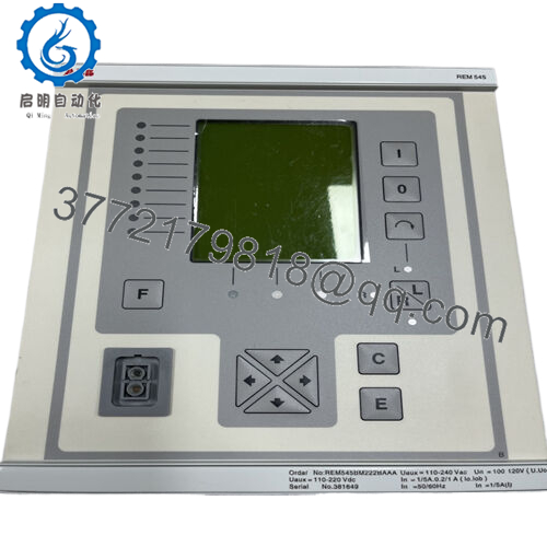
The ABB REM545 is a multifunctional machine terminal from the REM 54_ family, providing comprehensive protection for small/medium generators (including generator-transformer units) and large MV motors in industrial/power applications. It combines differential protection, thermal overload, directional overcurrent/earth-fault, underexcitation, start-up supervision, and more in one unit, reducing auxiliary relays and panel space.
Its key strength lies in integrated control (local/remote with synchro-check), measurement (currents, voltages, power, energy), condition monitoring (trip circuit, CB wear), and flexible PLC logic for automation sequences. Engineers selected it for compact solutions in hydro, diesel, steam plants, and heavy motor drives because it minimizes hardwiring via LON inter-bay comms and supports legacy protocols like SPA/Modbus.
Installation & Configuration Guide
Stage 1: Pre-Installation Preparation (15-20 min) ⚠️ Safety First: Coordinate with operations for planned downtime. Confirm machine in safe state (stopped, isolated). Lock out/tag out all power sources (aux and field). Wait at least 5 min for capacitors to discharge. Tools Required: Grounded ESD wrist strap, PH1/PH2 screwdriver, Fluke multimeter, wire labels/markers, smartphone/camera for photos. Data Backup: Use CAP 501/505 tool to export configuration, settings, and logic. Photograph all DIP switches (if any on modules), terminal wiring, HMI alarm LEDs status, and rear terminal labels. Document communication parameters (address, baud rate).
Stage 2: Removing the Old Module (10-15 min)
- Open front bezel/cover if present.
- Label every wire/terminal point carefully—do not rely on memory.
- Disconnect wiring gently (use torque screwdriver; avoid pulling conductors).
- Release rack locking tabs/levers and pull module straight out slowly to avoid damaging backplane pins.
- Inspect backplane for dust, corrosion, or bent pins—clean if needed with approved contact cleaner. ⚠️ Note: Retain the old unit as reference until the replacement is fully commissioned and tested.
Stage 3: Installing the New Module (15-20 min)
- Ground yourself with ESD strap; work on ESD mat. Confirm replacement matches exact order code (e.g., REM545BG… variant, same CT/VT ratings, power supply).
- Configuration Clone (Crucial): Mirror all settings from photos—check rear module DIP switches/jumpers for threshold voltages, addresses, termination. This is the most common cause of immediate faults.
- Align and insert firmly into rack slot—listen for secure click and ensure full seating on backplane. Lock tabs.
- Reconnect all wiring exactly as labeled; torque terminals per manual (typically 0.5-1 Nm). Self-Checklist: [ ] DIP/jumper settings match old unit, [ ] All wiring secure and correct polarity, [ ] Module fully seated and locked.
Stage 4: Power-On & Testing (20-40 min) Pre-Power Check: Use multimeter to verify no shorts on 24V/ aux rails and correct polarity. Power-On Steps:
- Energize aux power only (keep field circuits isolated).
- Watch LEDs: Green RUN/PWR good; IRF (internal fault) off; no persistent red ERR.
- Connect CAP 505 via front port; verify firmware version matches site (mismatch causes comms/func blocks failure).
- Upload/download backup config if needed; compare settings.
- Perform dry-run: Simulate inputs, check protection pickup/trip logic, verify measurements match expected values. ⚠️ Troubleshooting Note: Solid red ERR often means firmware mismatch or hardware fault—downgrade firmware if needed. No comms? Confirm rear port wiring, address, baud. If differential or directional elements fail, re-verify CT polarity and direction settings.

- REM545
Frequently Asked Questions (FAQ)
Is the REM545 hot-swappable? No. Power must be removed before insertion/removal. Hot-swapping risks backplane damage or module failure due to live pins and no hot-swap design.
Is this model obsolete, and is stock genuinely new? Yes, ABB declared it not active since 2022. Available units are typically new surplus (unused OEM stock) or refurbished/tested. We perform full inbound inspection, 24+ hour load test on simulated rack, firmware verification, and insulation/hipot checks—test reports/photos available on request.
What is the direct replacement for REM545? No plug-and-play drop-in exists due to I/O count, protocols (SPA/LON), and function blocks. ABB recommends Relion REG615 (generator) or REM615 (motor) series, but expect rewiring, config rewrite, and possible panel mods. Check ABB migration guides for your application.
Will swapping the REM545 erase my programmed logic and settings? The logic/settings reside in non-volatile memory. If you upload the config before removal and download to the new unit (same firmware), programming is retained. Always backup first—I’ve seen swaps where techs skipped this and spent days reconstructing logic.
Why is surplus pricing lower than original OEM? OEM discontinued support and new production. Surplus units come from decommissioned plants or excess inventory, rigorously tested but without factory warranty. Our 1-year post-test warranty covers function under normal use.
Can I use this with modern IEC 61850 systems? Yes, via optional SPA-ZC 400 adapter on rear port for IEC 61850 mapping. Native comms are SPA, LON, Modbus—common in legacy plants but may need gateway for new SCADA.
Keep photos, backups, and firmware notes during swaps—you’ll avoid most headaches.


