
 WhatsApp: +86 16626708626
 Email:
  Phone: +86 16626708626
Description
Key electrical and functional data
- Protection functions: Two-stage busbar overvoltage, two-stage busbar undervoltage, two-stage residual overvoltage; voltage-based load shedding and restoration possible via logiclibrary.
- Measurements: Three phase-to-phase voltages, residual voltage; calculates positive and negative sequence voltages and averages/max/min values for super
- Rated voltage (Un): 100 / 110 / 115 / 120 V selectable (phase-to-phase VT secondary)library.
- Rated frequency: 50 / 60 Hz ± 5%library.
- Voltage input thermal capability: 2 × Un continuously (up to 240 V); 3 × Un for 10 s (up to 360 V)library.
- Operating range of energizing inputs: ± 20% of rated voltagelibrary.
- Auxiliary DC supply options: Typical ranges 24–60 V DC and 88–250 V DC versions (exact options depend on order code)library.
- Auxiliary supply interruption tolerance: < 50 ms at rated Uaux without relay resetlibrary.
Inputs and outputs
- Voltage inputs: 4 analog voltage inputs (three phase-to-phase plus residual or check VT, depending on configuration)library.
- Digital inputs: 2 galvanically isolated standard; +3 additional digital inputs with optional I/O module (total up to 5)library.
- Power outputs (PO1–PO3): 3 normally open heavy-duty output contacts, 250 V AC/DC, 5 A continuous, 15 A for 3 s, 30 A for 0.5 s; DC breaking capacity 1 A / 0.25 A / 0.15 A at 48 / 110 / 220 V DC (L/R < 40 ms)library.
- Signal outputs: 2 change-over signal output contacts + up to 3 more on optional I/O module; one dedicated IRF (internal fault) contactlibrary.
- Minimum contact load: 100 mA at 24 V AC/DClibrary.
Mechanical and environmental
- Dimensions (frame): 177 mm (W) × 177 mm (H, 4U)library.
- Dimensions (case): 164 mm (W) × 160 mm (H) × 149.3 mm (D)library.
- Weight: Approx. 3.5 kg for complete relay; spare unit around 1.8 kg–3.5 kg depending on referencelibrary.
- Insulation resistance: > 100 MΩ at 500 V DC (per IEC 60255-5)
- EMC and immunity: Designed to IEC 60255 and IEC 61000 series (surge, ESD, magnetic field, common-mode and differential-mode disturbances)library.
Performance
- Operate time (voltage stages U>, U>>): Definite-time 0.10–600 s; typical reset time 30 ms, maximum 50 mslibrary.
- Trip circuit supervision: Built-in supervision and trip lockout; trip counters for circuit-breaker condition monitoringlibrary.
- Disturbance recording: Up to 80 s recording of 4 analog and up to 8 digital channels; trigger by internal or digital input signals
- Product Introduction
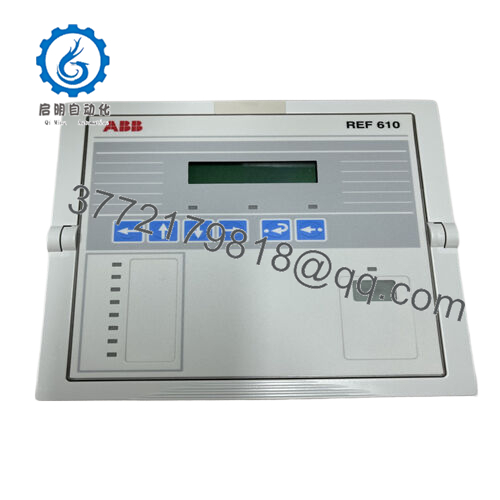
ABB REU610 is a numerical voltage protection relay from the Relion 610 family, used for busbar overvoltage/undervoltage protection and residual overvoltage protection in utility and industrial distribution systems. It measures three phase-to-phase voltages and residual voltage, calculates sequence components, and supervises system voltage quality for feeders, transformers, and motors.
In practice, engineers choose REU610 when they need a compact, 4U panel-mounted voltage IED that handles both protection and detailed voltage supervision with disturbance recording and flexible I/O mapping. The relay’s four voltage inputs, configurable digital I/O, and 250 V / 5 A power outputs make it a solid fit for retrofits and new builds where voltage-based schemes (load shedding, restoration, bus transfer interlocks) must be implemented within IEC/ANSI-standard relays.new.

- REU610
- Troubleshooting Quick Reference
| Symptom | Possible Cause | Relevance to this Part | Quick Check Method | Recommendation |
|---|---|---|---|---|
| No LEDs or display on REU610 after energizing | No or wrong auxiliary DC supply; blown panel fuse | ✅ High | Measure DC at the auxiliary supply terminals and compare with the rated Uaux range on the relay label and datasheet | If no or low voltage, fix supply or fuse; only suspect the relay PSU if correct DC is present and it still remains dead |
| Relay shows IRF (internal fault) indication | Internal self-supervision has detected a hardware or serious configuration fault | ✅ High | Read IRF details via HMI or PC tool if available; power-cycle once to rule out a transient; check event list time stamps | If IRF persists, plan to replace the relay and reload settings from a known-good backup before putting it back in service |
| Voltage indications clearly wrong vs. panel meters | VT ratio mismatch in settings or wiring error on voltage inputs | ✅ Medium | Compare VT ratio settings in REU610 with one-line and VT nameplate; measure VT secondary with a multimeter and compare with relay’s displayed primary values | Correct VT ratios and wiring first; only consider hardware failure if readings are unstable or inconsistent after corrections |
| Overvoltage/undervoltage stages never operate in testing | Pickup levels or time delays set too high / long; enable flags not set | ✅ Medium | Inject test voltages via secondary injection or VT test plug and monitor stage pickup flags and timers in the relay | Adjust settings according to the protection study; replacement will not fix misconfigured pickup thresholds or delays |
| Nuisance trips on minor voltage dips or switching | Pickup set too close to nominal; no blocking logic with breaker status or bus conditions | ✅ Medium | Review event and disturbance records around each trip; check U>/U>> settings vs. system operating voltage band | Tighten logic and add blocking/definite-time delays; only replace the relay if outputs chatter or logic acts erratically despite correct settings |
| Some digital inputs or outputs appear dead | Wrong auxiliary control voltage or contact rating exceeded; miswired terminals | ✅ Medium | Measure the DC control voltage at each digital input or output contact and compare with specified ranges and load ratings library. | Fix wiring and voltage first; if the contact fails continuity tests under rated conditions, the I/O section may require repair or unit replacement |
| Communication to SCADA/RTU intermittently fails | Fiber or RS-485 cabling issues; protocol or address mismatch | ✅ Medium | Inspect connectors, check physical link LEDs (if present), verify communication settings (baud, address, protocol) against SCADA configuration library. | Correct the communication path and settings; only attribute the issue to the relay if all external factors are eliminated and ports fail loopback tests |
If the above checks do not narrow the root cause, capture front-panel screenshots, event lists, and disturbance records, then share them with technical support before you authorize a replacement order. That step alone often saves a perfectly good relay from being swapped out unnecessarily.library.
- Frequently Asked Questions (FAQ)
Q1: What is ABB REU610 used for in a substation?
REU610 is a numerical voltage protection relay that provides overvoltage, undervoltage, and residual overvoltage protection for busbars, feeders, transformers, and motors in distribution substations. It also measures and supervises system voltages, offering disturbance recording for post-fault analysis.new.
Q2: Is REU610 considered a legacy/obsolete relay, and how does that affect stock?
REU610 is listed by ABB under legacy voltage relays with continued service and retrofit support, which means it is not the latest platform but still widely used in existing panels. In practice, new units often come from remaining ABB production, project surplus, or decommissioned installs, so availability tends to be batch-based and can be limited.
Q3: Can I drop in a new REU610 as a direct replacement for my existing one?
Yes, but only if you match the exact type code (including auxiliary supply variant and communication options) and then transfer the settings correctly. The relay hardware form factor and terminals are consistent within the family, but function behavior is driven by configuration, so always export the existing settings and disturbance data before you pull the old unit.library.
Q4: Do I lose settings when I replace an REU610, and how should I handle configuration?
A brand-new or factory-reset REU610 will not automatically carry your old parameters; you must restore them from a saved file using ABB engineering tools or manually program them through the HMI. Before you remove a live relay, back up all settings and note VT ratios, pickup levels, time delays, and logic bindings; that habit prevents a lot of rework after installation.library.
Q5: Is REU610 hot-swappable like a plug-in PLC card?
No. Treat REU610 as a substation protection IED tied directly to VT circuits and breaker trip coils, not as a low-voltage plug-in card. You should de-energize the relevant DC supply and follow your site’s lockout/tagout rules before removing or inserting the relay to avoid arcing, wiring damage, or unintended trips. That is standard practice for any panel-mount protection relay.library.
Q6: What are the main technical pitfalls when commissioning or replacing an REU610?
The usual traps are incorrect VT ratios, overly tight over/undervoltage pickup settings that track normal voltage swings, and forgetting to coordinate time delays with upstream and downstream devices. Another recurring issue is miswired digital I/O or under-rated trip circuit wiring that cannot handle the 5 A / 250 V output capability, which can lead to contact damage or unreliable tripping if not engineered correctly.library.
Q7: What condition and testing should I demand if I buy an REU610 on the surplus market?
For New Surplus or Refurbished REU610 units, look for documented power-up tests, verification of all four voltage inputs across the operating range, basic digital I/O checks, and confirmation that disturbance recording and self-supervision functions operate as expected. A written warranty and clear statement of firmware/product version C support are good signs that the unit has been treated as a protection relay, not just a piece of shelf stock.


