
 WhatsApp: +86 16626708626
 Email:
  Phone: +86 16626708626
Description
- Product Core Brief
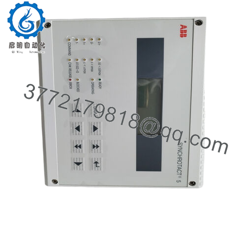
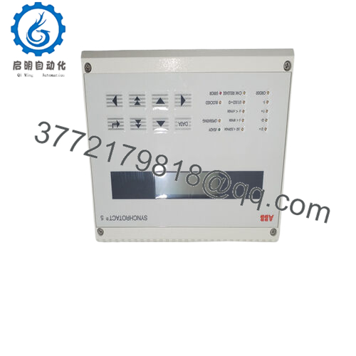
- Model: SYN5201a-Z,V217 (3BHB006714R0217)
- Brand: ABB
- Series: SYNCHROTACT 5
- Core Function: Automatic generator synchronization
- Product Type: Synchronization relay/unit
- Key Specs: Single-channel auto sync, 24 V DC nominal, checks ΔV / Δf / Δφ
- Condition: New Original / New Surplus
- Key Technical Specifications
- Nominal supply voltage: 24 V DC (some variants accept 48 V DC or 110-220 V AC/DC ranges – verify label)
- Operating voltage range: Typically 18–32 V DC
- Power consumption: Approx. 10–15 W
- Synchronization parameters: Voltage difference (adjustable 0–20%), slip frequency (0.01–0.5 Hz typical), phase angle window (±10° to ±60°)
- Output relays: Close command, sync check, alarm contacts (potential-free)
- Input signals: Bus and generator voltage transformers (100–120 V AC nominal), frequency via VT
- Ambient temperature: −20 to +55 °C (operating)
- Mounting: DIN rail or panel, compact housing
- Communication: None standard (some variants add Modbus option)
- Protection class: IP20
- Dimensions: Approx. 150 × 90 × 60 mm (varies slightly by revision)
- Weight: Approx. 0.8–1.2 kg
- Product Introduction
The ABB 3BHB006714R0217 (SYN5201a-Z,V217) is a single-channel automatic synchronizing unit in the SYNCHROTACT 5 family. It handles breaker closure for paralleling a generator to a live bus or grid by measuring and matching voltage magnitude, frequency, and phase angle.
Plants choose this model for its proven reliability in generator synchronization since the early 2000s. It delivers precise auto-sync with adjustable slip and angle windows, reducing mechanical stress on turbines and breakers compared to manual methods. The single-channel design keeps costs down for non-critical or redundant setups.
- Installation & Configuration Guide
Stage 1: Pre-Installation Preparation (15–20 min) ⚠️ Safety First: Coordinate with operations for scheduled downtime. Confirm generator and bus are in safe state (breaker open, excitation off if needed). Lock out/tag out all power sources. Wait 5 minutes after power removal for capacitors to discharge. Tools Required: Grounded ESD wrist strap, PH1/PH2 screwdriver, digital multimeter, wire labels, smartphone for photos. Data Backup: Photograph all front-panel settings (potentiometers for ΔV, Δf, phase window, etc.). Note any external wiring to terminals. Export parameter list if connected to programming tool (rare for this unit). Record VT ratios and wiring.
Stage 2: Removing the Old Module (10 min)
- Open front cover if present.
- Label and disconnect all wiring (voltage inputs, sync relay outputs, power, aux contacts). Use torque screwdriver to avoid damage.
- Release DIN rail clip or panel screws. Pull module straight out to avoid bending backplane pins (though this unit is mostly standalone).
- Inspect mounting area for dust, corrosion, or loose terminals. ⚠️ Note: Retain the old unit as reference until the replacement runs without issues.

- SYN5201a-Z,V217 (3BHB006714R0217)
Stage 3: Installing the New Module (15 min)
- Wear ESD strap. Confirm replacement model matches exactly (3BHB006714R0217, revision V217).
- Configuration Clone (Crucial): Set all potentiometers and DIP switches (if any) to match photographed old unit values. Pay close attention to voltage range selectors, frequency (50/60 Hz), and sync windows.
- Mount on DIN rail or panel; ensure secure click-in.
- Reconnect wiring exactly as labeled. Torque terminals per spec (typically 0.5–0.8 Nm). Verify shielding/grounding. Self-Checklist: [ ] Potentiometers match, [ ] Wiring polarity correct, [ ] Mounting secure.
Stage 4: Power-On & Testing (20–30 min) Pre-Power Check: Use multimeter to verify no shorts on 24 V supply rail and correct polarity. Power-On Steps:
- Apply control power only (no field voltages yet).
- Observe LEDs: Power ON green, no error; sync ready when conditions met.
- Energize VT inputs (bus and generator). Monitor for proper voltage/frequency display if equipped.
- Simulate sync conditions or run live test with supervision. Verify close relay activates only when parameters match.
- Test alarm/trip contacts if wired. ⚠️ Troubleshooting Note: If no power LED, check supply voltage and fuse. If sync fails, re-verify potentiometer settings. Mismatched frequency setting causes permanent slip error. If relay chatters, tighten phase window.
- Frequently Asked Questions (FAQ)
Can this unit be hot-swapped under power? No. Never hot-swap. Removing it live risks arcing on terminals or damaging the backplane/logic. Always kill control power first. I’ve seen a tech ignore this and blow a fuse – downtime extended by hours.
Is this model obsolete, and is your stock genuinely new? SYN5201a-Z,V217 remains available through surplus and aftermarket as of 2026; ABB still supports SYNCHROTACT 5 family. Our units are new original or new surplus from verified OEM channels. We provide inbound traceability photos and test reports. No refurbished unless clearly stated.
What is the direct replacement if this is out of stock? Check SYN5201a-Z,V271 (3BHB006714R0271) or later revisions for pin compatibility. For new projects, ABB may push newer SYNCHROTACT series. Always cross-reference the OEM datasheet for exact I/O mapping and parameter ranges before substituting.
Will I lose synchronization settings when swapping the unit? Yes – settings live in hardware potentiometers and switches, not volatile memory. Photograph every dial and switch position before removal. Mirror them exactly on the new unit. Skipping this step causes immediate sync failure on power-up.
Why is the price lower than ABB factory list? This is surplus stock from decommissioned projects or excess inventory, not direct from ABB channel. We test every unit functionally (power-up, relay actuation, signal simulation) before shipment. You get genuine hardware at lower cost with full transparency on condition and testing.


