
 WhatsApp: +86 16626708626
 Email:
  Phone: +86 16626708626
Description
3. Key Technical Specifications
| Parameter | Value |
|---|---|
| Product Type | RCU Link Terminator |
| System Compatibility | ABB AC 800M / 800xA |
| Function | Signal termination for RCU link |
| Termination Resistance | 120 Ω (integrated) |
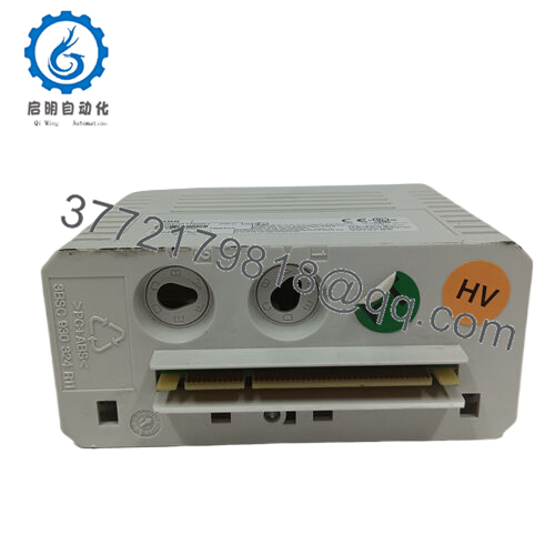
| Connector Type | 9-pin D-sub |
| Operating Voltage | Passive (no external power required) |
| Operating Temperature | −25 to +70 °C |
| Storage Temperature | −40 to +85 °C |
| Protection Rating | IP20 |
| Dimensions | ~57 × 23 × 20 mm |
| Weight | ~0.02 kg |
| Installation | Direct plug-in to RCU link port |
4. Product Introduction & Supply Chain Strategy
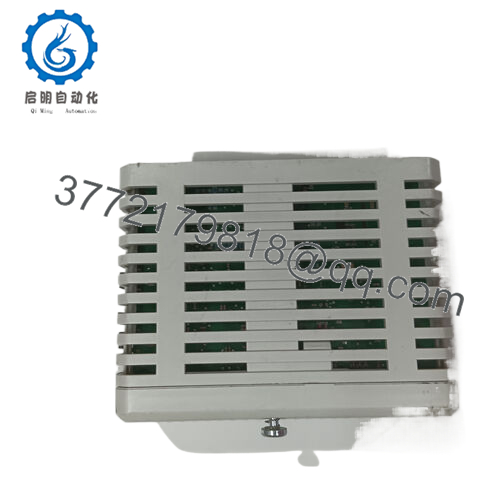
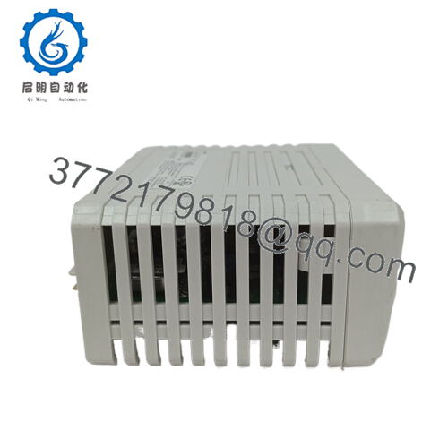
The ABB TB852 3BSC950263R1 is an RCU link terminator used in AC 800M redundant controller architectures. It ensures proper impedance matching at the end of the RCU communication bus, preventing signal reflections and maintaining stable high-speed synchronization between redundant CPUs.
From a supply-chain standpoint, this is a small but mission-critical passive component. Failure or absence leads to communication instability in redundant systems. Given its niche role and declining production volume, lead time variability is high. Securing New Surplus units as buffer stock minimizes system-level risk and avoids inflated emergency procurement costs—protecting overall Total Cost of Ownership (TCO).

- TB852
5. Installation & Configuration Guide
Stage 1: Pre-Installation (Prep & Safety)
- Apply lock-out/tag-out (LOTO).
- Use ESD protection—this interfaces directly with controller communication ports.
- Identify RCU link topology and confirm termination points.
- Inspect existing terminator placement (end-of-line only).
Stage 2: Removal
- Power down controller system.
- Gently disconnect the existing TB852 from the RCU link port.
- Avoid lateral force on the D-sub connector.
Stage 3: Installation (Clone & Seat)
- Install the TB852 at the correct end-of-line position only.
- Ensure firm seating in the 9-pin interface.
- Do NOT install multiple terminators on the same segment.
Stage 4: Power-On & Testing
- Re-energize system and monitor controller redundancy status.
- Verify no communication alarms between PM units.
- Check system logs for RCU link stability.
6. Firmware/Software Versions & Upgrade Notes
- Firmware Dependency: None (passive hardware device).
- System Dependency: Must match AC 800M redundancy architecture.
- Compatibility Risk: Incorrect or missing termination causes intermittent communication faults—often misdiagnosed as CPU or network failure.
- Best Practice: Validate physical layer (termination) before troubleshooting firmware or controller logic.
7. Frequently Asked Questions (FAQ)
Q1: Is this TB852 unit truly new or previously installed?
This product is a Brand New Surplus unit. It is not used, not pulled from a decommissioned plant, and not refurbished. It maintains original connector integrity and zero wear.
Q2: Why is such a small component strategically important?
Because it stabilizes the entire redundant communication bus. Without proper termination, signal reflections can cause intermittent controller sync failures—leading to nuisance trips or failovers.
Q3: Is this part obsolete or still in production?
It is lifecycle-mature and increasingly difficult to source. This is a classic case for proactive buffer stock or a controlled last-time-buy strategy.
Q4: Can I operate the system without a terminator temporarily?
Not recommended. You may experience unstable communication, especially under load or during failover conditions.
Q5: Does this device require configuration or programming?
No. It is a passive device with fixed electrical characteristics. Correct placement is the only requirement.
Q6: What is the recommended stocking strategy?
- Minimum: 1 unit per redundant controller pair
- Multi-site plants: central buffer pool + cross-site sharing
- Critical DCS nodes: keep 2 units for redundancy assurance
Q7: What warranty is provided?
Typically 12 months. This aligns with long-term reliability expectations and eliminates the short lifecycle risk associated with non-original supply channels.


