
 WhatsApp: +86 16626708626
 Email:
  Phone: +86 16626708626
Description
Product Core Brief
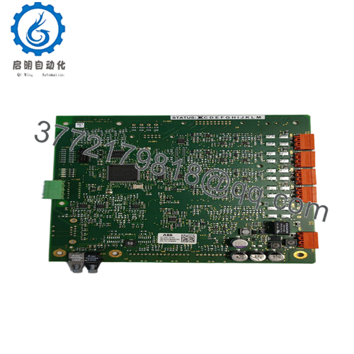
- Model: UFC911B104 (3BHE037864R0104)
- Brand: ABB
- Series: UNITROL F (Excitation Systems)
- Core Function: Excitation control and power interface for synchronous generators
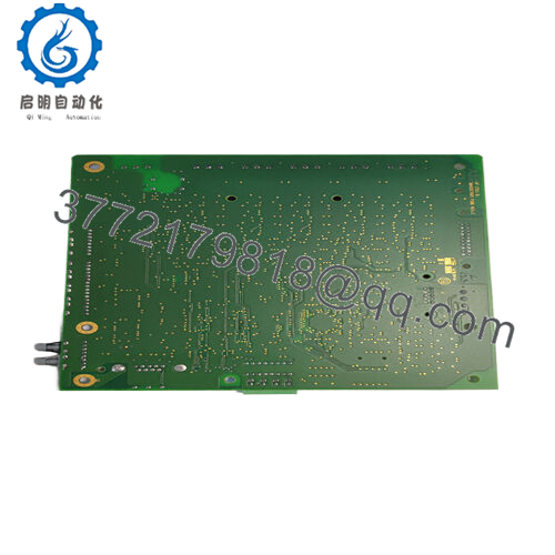
- Product Type: Excitation controller / circulation plate (CVMI2B)
- Key Specs: 100-240 V AC input, up to 10 A output capability, integrated protections (short circuit, overload)
- Condition: New Original / New Surplus
Key Technical Specifications
| Parameter | Value |
|---|---|
| Ordering number | 3BHE037864R0104 |
| Type designation | UFC911B104 / CVMI2B |
| Input voltage range | 100-240 V AC (50/60 Hz) |
| Output current (max) | 10 A (typical application-dependent) |
| Power consumption | Approx. 20-50 W (load dependent) |
| Protections | Short circuit, overload, overvoltage |
| Ambient temperature | -20 to +60 °C operating (verify datasheet) |
| Mounting | Plug-in module for UNITROL excitation rack |
| Weight | Approx. 0.2 kg |
| Country of origin | Switzerland |
| Customs tariff | 8504 9099 |
| Communication/Interface | Internal to UNITROL F system (no external fieldbus on this board) |
Product Introduction
The ABB UFC911B104 (3BHE037864R0104), designated UF C911 B104 or CVMI2B, serves as a key excitation control and power interface module within ABB’s UNITROL F series excitation systems. It handles regulated DC power supply and control signals for the field winding of synchronous generators in power plants, industrial drives, and backup generators.
In field work on UNITROL-equipped turbines and motors, this board stands out for its reliable voltage regulation loop support and built-in protections that prevent field overcurrent during faults. It integrates tightly with the main controller board in the rack, delivering stable excitation under varying load conditions without needing external converters in many setups.

- UFC911B104 3BHE037864R0104
Installation & Configuration Guide
Stage 1: Pre-Installation Preparation (20-30 minutes) ⚠️ Safety First: Shut down the excitation system completely. Lock out/tag out all incoming AC supplies to the excitation cabinet and confirm zero voltage on field terminals with a multimeter. Discharge capacitors (wait 10+ minutes). Notify control room of generator offline status. Tools Required: Grounded ESD wrist strap, PH2 screwdriver, digital multimeter (for continuity and voltage), torque screwdriver (0.5-1 Nm range), wire labels, camera for photos. Data Backup: Photograph all jumper settings, LED status, and terminal connections on the old board. Document excitation parameters (AVR setpoints, limiters) from the main HMI or engineering station. Export any fault logs if accessible.
Stage 2: Removing the Old Module (15-20 minutes)
- Open the excitation cabinet door and locate the UFC911B104 slot (typically in the power section of the UNITROL rack).
- Label every wire on power input, output to field, and internal control connectors—take close-up photos from multiple angles.
- Disconnect wiring carefully; use a small flat tool if terminals are tight, but never force.
- Release the module locking levers or screws and pull straight out to avoid damaging edge connectors.
- Inspect the rack slot for dust, corrosion, or bent pins on the backplane. ⚠️ Note: Retain the old module (safely stored and labeled) until the replacement proves stable under full load for at least 48 hours.
Stage 3: Installing the New Module (20-25 minutes)
- Ground yourself with ESD strap and confirm the replacement is exactly 3BHE037864R0104 UFC911B104.
- Configuration Clone (Critical): Match any jumpers or selectors from the old board photos (check for voltage range or protection settings if present). Most CVMI2B variants have factory defaults—no DIP switches in standard configs.
- Align the module with the rack guides and push firmly until it seats (listen for the click or feel the lock engage). Secure any retaining screws.
- Reconnect all wiring exactly as photographed, applying correct torque to terminals. Verify polarity on DC field outputs. Self-Checklist: [ ] Jumpers match old board, [ ] Wiring secure and labeled, [ ] Module fully seated and locked, [ ] No loose strands.
Stage 4: Power-On & Testing (30-60 minutes) Pre-Power Check: Measure insulation resistance (>10 MΩ at 500 V) on field circuit if possible. Confirm no shorts between input phases and ground. Power-On Steps:
- Energize auxiliary power to the excitation rack only (keep generator field disconnected initially if procedure allows).
- Observe board LEDs and main system status: Power OK green, no fault reds.
- Connect to the UNITROL engineering tool or HMI; verify board recognition and no alarms (e.g., “Power Supply Fault”).
- Perform no-load excitation test: Ramp field voltage slowly, monitor output stability.
- If cleared, synchronize to generator and load test under controlled conditions. ⚠️ Troubleshooting Note: Persistent “Excitation Fault” or no field current? Recheck input voltage (100-240 V AC present?), wiring polarity, and jumper match. Overcurrent trip on power-up usually points to reversed field connections or shorted board—kill power immediately.
Frequently Asked Questions (FAQ)
Can this module be hot-swapped? No. The UFC911B104 is not designed for live insertion/removal. Powering the rack with the module partially connected risks arcing at the edge connectors or damaging the backplane. Always isolate all supplies first.
Is the UFC911B104 obsolete, and is your stock new? The UNITROL F series sees ongoing support, but specific boards like this become surplus as newer UNITROL 1000/6000 lines take over. We supply new original or factory excess stock—verified via OEM traceability, with full functional testing (power-up, output load simulation >24 hours) and insulation checks. Photos of seals and test reports available.
What is the direct replacement if this is unavailable? Consult ABB for the current equivalent in UNITROL 1020 or newer platforms—often requires adapter kits or full rack migration. Avoid third-party clones; pinouts and firmware interfaces differ. Stick to exact 3BHE037864R0104 for drop-in in existing F-series systems.
Will replacing this board erase excitation settings? Typically no—the main parameters (AVR gains, limiters) reside in the primary controller board or non-volatile memory elsewhere in the rack. This power/interface board handles analog signals and supply, not setpoints. Still, document HMI values and re-verify after swap.
Why is the price lower than ABB direct? Sourced as new surplus from verified channels (OEM excess, decommissioned spares), bypassing full distributor markup. Every unit gets our QC: inbound anti-counterfeit check, 24-hour powered burn-in with load, and parameter verification. Condition is new, not repaired or refurbished.
How does this integrate with the rest of UNITROL? It plugs directly into the designated slot, supplying regulated power to the thyristor bridge or chopper and interfacing control signals. In redundant setups, match pairs exactly. I’ve commissioned dozens where mismatched revisions caused regulation instability—always verify part suffix.
Any common failure signs on this board? Watch for no output voltage despite input power (failed internal supply), intermittent trips (capacitor aging), or overheating smell (overload components). In humid environments, corrosion on connectors is frequent—clean and apply contact protector during install if needed.


