
 WhatsApp: +86 16626708626
 Email:
  Phone: +86 16626708626
Description
3. Key Technical Specifications
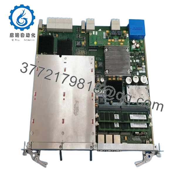
- Part Number: 3CM02859AGAF03 (NBRZAG variant)
- Module Type: Expansion / Interface module
- System Role: Extends port capacity and processing capability
- Architecture: Backplane-mounted telecom module
- Interface Density: High-density (exact port count depends on system configuration)
- Supported Protocols: Ethernet / IP-based telecom signaling (platform-dependent)
- Application: Carrier networks, switching systems, aggregation nodes
- Form Factor: Plug-in card for telecom chassis
- Cooling: Passive via chassis airflow
- Lifecycle Status: Discontinued / legacy telecom hardware
- Comparable Variant: 3CM02859ADAF03 (similar expansion function)
4. Product Introduction
The Alcatel-Lucent NBRZAG 3CM02859AGAF03 is a telecom expansion module used to increase interface density and processing capacity within carrier-grade network systems. It integrates into a chassis backplane and operates as an extension card rather than a standalone unit.
In field deployments, modules in this family are typically installed in switching or aggregation platforms to add additional ports or service capacity. Based on similar variants, these modules are designed for high-density connectivity and multi-protocol support, making them critical when scaling legacy telecom infrastructure without replacing the entire chassis.
5. Installation & Configuration Guide
Stage 1: Pre-Installation Preparation (Estimated: 10–15 minutes)
- ⚠️ Safety First:
Notify NOC. Drain traffic from affected ports. Disable interfaces. Power down slot if hot-swap is not confirmed. Wait 5 minutes. - Tools Required:
ESD strap, flat screwdriver, labeling tags, multimeter, smartphone - Data Backup:
- Export system configuration
- Record slot assignment and port mapping
- Photograph existing module and cabling
Stage 2: Removing the Old Module (Estimated: 5–10 minutes)
- Shutdown interfaces via CLI/NMS
- Label all connected cables
- Disconnect cables carefully
- Release ejector levers
- Pull module straight out
- Inspect backplane connectors
- ⚠️ Note: Keep old module until system is fully restored
Stage 3: Installing the New Module (Estimated: 5–10 minutes)
- Apply ESD protection
- Verify exact model: 3CM02859AGAF03 (NBRZAG)
- Insert module evenly into slot
- Lock ejector levers
- Reconnect cables based on labels
- Self-Checklist:
- Fully seated
- Correct slot
- All connections secure
Stage 4: Power-On & Testing (Estimated: 10–20 minutes)
- Pre-Power Check:
Verify no short on power rails - Power-On Steps:
- Power up chassis or enable slot
- Verify module detection (
show card/ equivalent) - Check port status
- Validate traffic flow
- Monitor alarms
- ⚠️ Troubleshooting Note:
- Module not detected → firmware or slot compatibility issue
- Ports down → configuration or cabling mismatch
6. Frequently Asked Questions (FAQ)
Q1: Is this module hot-swappable?
Depends on the platform.
Some Alcatel systems support it, but I’ve seen older shelves glitch when swapping under load. If uptime is critical, isolate traffic first.
Q2: Is 3CM02859AGAF03 still manufactured?
No.
This is legacy telecom hardware. Most inventory comes from surplus or decommissioned systems.
Q3: Can I use a similar model like 3CM02859ADAF03?
Not safely without verification.
Even small suffix changes can affect interface mapping or firmware expectations.
Q4: Will this module increase bandwidth?
Indirectly.
It expands interface capacity, which allows more traffic handling—but overall throughput still depends on the chassis fabric.
Q5: Why do some units fail after installation?
Two common reasons:
- Firmware mismatch with host system
- Backplane connector wear
Q6: What’s the most common field mistake?
❗ Not documenting port mapping.
I’ve seen engineers reinstall correctly but mispatch cables—resulting in hours of troubleshooting.

- NBRZAG 3CM02859AGAF03
SOP Quality Transparency (Inspection & Testing Process)
1. Inbound Inspection & Traceability
- Verified P/N: 3CM02859AGAF03
- Serial number recorded
- Visual inspection: no corrosion, no solder rework
- Connector pins checked under magnification
2. Live Functional Testing
- Installed in telecom test rack (Alcatel-compatible chassis)
- Module detection and initialization verified
- Port-level simulation testing
- 24-hour continuous runtime test
- Test reports and videos available upon request
3. Electrical Parameter Testing
- Insulation resistance: >10 MΩ @ 500 V
- Backplane continuity verified
- Voltage stability measured using Fluke 115
4. Firmware & Configuration Verification
- Hardware revision logged
- Compatibility checked with system firmware
- Port mapping validated
5. Final QC & Packaging
- QC sign-off with traceable ID
- ESD-safe packaging
- Reinforced carton with shock protection
- QC Passed label applied
Technical Pitfalls & Survival Guide
1. Firmware Compatibility Issues
❗ I’ve seen modules rejected because the system OS was one release behind.
Avoidance: Check compatibility matrix before installation.
2. Incorrect Module Variant
Suffix differences matter.
Avoidance: Match full part number including suffix (AGAF03 vs ADAF03).
3. Backplane Wear
Older telecom racks often have degraded connectors.
Avoidance: Inspect and clean before inserting module.
4. Port Mapping Errors
❗ Extremely common.
Avoidance: Label everything before removal.
5. ESD Damage
❗ Silent killer in telecom environments.
I’ve seen boards pass testing and fail immediately after improper handling.
Avoidance: Always use grounded wrist strap.


