
 WhatsApp: +86 16626708626
 Email:
  Phone: +86 16626708626
Description
3. Key Technical Specifications
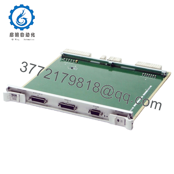
- Part Number: WWAD34
- Product Type: Telecom circuit card assembly
- System Role: Interface / control board within switching system
- Architecture: Backplane-mounted PCB (slot-in module)
- Connector Type: Proprietary multi-pin telecom backplane
- Function: Signal routing, control logic, and interface handling
- Application: Central office switching, transmission nodes
- Cooling: Passive via chassis airflow
- Operating Environment: Indoor telecom rack (0 to +50°C typical, verify per system)
- Lifecycle Status: Discontinued / legacy telecom hardware
- Typical Source: Surplus or decommissioned telecom infrastructure
4. Product Introduction
The Alcatel-Lucent WWAD34 is a telecom circuit board used in legacy switching and transmission systems. It operates as an internal interface/control module, managing signal paths and system-level communication through the chassis backplane.
From field experience, boards like WWAD34 are tightly bound to specific Alcatel system architectures—often part of proprietary switching platforms deployed in central offices. Replacement is not plug-and-play across systems. Exact model matching is required, otherwise the system may fail to initialize or route signals correctly.
5. Installation & Configuration Guide
Stage 1: Pre-Installation Preparation (Estimated: 10–15 minutes)
- ⚠️ Safety First:
Notify NOC. Isolate affected shelf. Power down rack or slot. Wait 5 minutes for discharge. - Tools Required:
ESD wrist strap, flat screwdriver, multimeter, labeling tags, smartphone - Data Backup:
- Record slot position and module ID
- Capture alarm logs
- Photograph wiring and adjacent boards
Stage 2: Removing the Old Module (Estimated: 5–10 minutes)
- Identify WWAD34 slot location
- Label any connected cables
- Release ejector levers
- Pull module straight out — do not twist
- Inspect backplane connector for damage
- ⚠️ Note: Retain the original module for rollback reference
Stage 3: Installing the New Module (Estimated: 5–10 minutes)
- Apply ESD protection
- Verify exact model: WWAD34
- Insert evenly into slot until fully seated
- Lock ejector levers
- Reconnect any cables
- Self-Checklist:
- Fully seated
- Correct slot
- No bent pins
Stage 4: Power-On & Testing (Estimated: 10–20 minutes)
- Pre-Power Check:
Verify no short on power rails - Power-On Steps:
- Power telecom shelf
- Monitor system alarms
- Verify module recognition
- Validate signal routing or service channels
- Perform service-level test
- ⚠️ Troubleshooting Note:
- Not detected → slot mismatch or backplane issue
- Signal failure → check system configuration or adjacent modules

- WWAD34
6. Frequently Asked Questions (FAQ)
Q1: Can this board be hot-swapped?
Depends on the platform.
Some Alcatel systems support it, but many legacy switching systems do not. If unsure, power down.
Q2: Is WWAD34 still manufactured?
No.
This is legacy hardware from older Alcatel-Lucent telecom systems. Availability is limited to surplus channels.
Q3: Is there a direct replacement?
No generic replacement.
You must use the exact same part number. Even visually similar boards may not work due to signaling differences.
Q4: Will replacing this module affect system configuration?
Typically no for logic storage, but incorrect hardware can prevent system startup or cause routing faults.
Q5: Why is pricing inconsistent?
Supply is tied to decommissioned infrastructure.
I’ve seen pricing fluctuate significantly depending on availability and tested condition.
Q6: Most common installation mistake?
❗ Wrong slot installation.
In telecom systems, slot position is often mapped to a specific function.
SOP Quality Transparency (Inspection & Testing Process)
1. Inbound Inspection & Traceability
- Verified P/N: WWAD34
- Cross-checked against supplier documentation
- Visual inspection: no corrosion, no rework marks
- Connector pins inspected under magnification
2. Live Functional Testing
- Installed in compatible telecom rack
- Power-on and module recognition verified
- Signal routing simulation performed
- Continuous runtime test: >24 hours
- Test reports and videos available upon request
3. Electrical Parameter Testing
- Insulation resistance: >10 MΩ @ 500 V
- Backplane continuity verified
- Voltage stability checked using Fluke 115
4. Firmware & Configuration Verification
- Hardware-level board (no independent firmware typical)
- Compatibility verified with host system
- Slot mapping confirmed
5. Final QC & Packaging
- QC sign-off with traceable ID
- ESD-safe packaging
- Reinforced industrial carton
- QC Passed label with inspection date
Technical Pitfalls & Survival Guide
1. Exact Model Dependency
❗ Even small differences break compatibility.
I’ve seen engineers try “close enough” boards—system refused to boot.
Avoidance: Match exact part number.
2. Slot Mapping Errors
Telecom racks are strict.
Avoidance: Document slot before removal.
3. Backplane Wear
Older systems often have oxidized connectors.
Avoidance: Inspect and clean before installing.
4. Signal Path Misinterpretation
Not all boards are simple pass-through.
Avoidance: Verify system diagrams.
5. ESD Handling
❗ Silent failure risk.
I’ve personally seen boards fail immediately after improper handling.
Avoidance: Always use grounded wrist strap.


