
 WhatsApp: +86 16626708626
 Email:
  Phone: +86 16626708626
Description
3. Key Technical Specifications
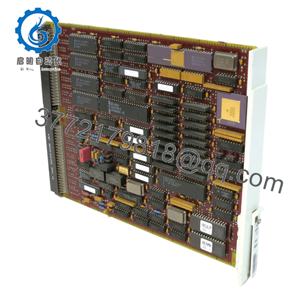
- Part Number: TM659C / 846616399-2
- Classification: Circuit Card Assembly (FSC 5998)
- System Role: Telecom switching / signal interface board
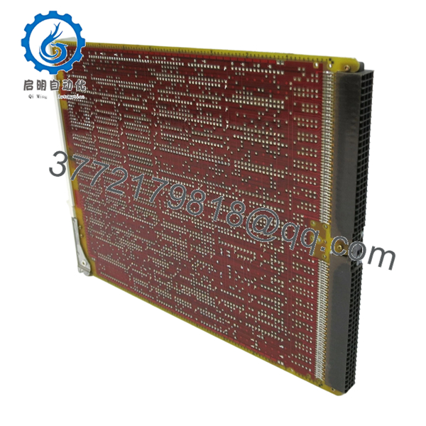
- Architecture: Backplane-mounted PCB (rack-based telecom system)
- Function Type: Signal distribution (1:2 split / interface logic)
- Connector Type: Multi-pin telecom backplane connectors
- Application: Central office switching, legacy transmission systems
- Form Factor: Slot-in card for telecom chassis
- Lifecycle Status: Discontinued / legacy telecom hardware
- Typical Deployment: Alcatel switching systems / SSC modules
4. Product Introduction
The Alcatel Enterprise TM659C (846616399-2) is a circuit card assembly used in telecom switching and transmission systems. It functions as a signal interface and distribution board, typically handling 1:2 signal routing within a chassis-based architecture.
In real-world telecom environments, this type of board is deployed inside legacy Alcatel switching platforms where deterministic signal routing and timing are critical. It is not a generic network card—replacement requires exact part number matching due to tight coupling with system backplane logic and signaling schemes.
5. Installation & Configuration Guide
Stage 1: Pre-Installation Preparation (Estimated: 10–15 minutes)
- ⚠️ Safety First:
Notify NOC. Isolate affected telecom shelf. Power down the rack or slot. Wait 5 minutes for discharge. - Tools Required:
ESD wrist strap, flat screwdriver, multimeter, labeling tags, smartphone - Data Backup:
- Document slot location and card ID
- Photograph wiring and adjacent modules
- Record system alarms/status before shutdown
Stage 2: Removing the Old Module (Estimated: 5–10 minutes)
- Identify TM659C slot position
- Label all associated cables (if external interfaces exist)
- Release ejector levers
- Pull the board straight out — no side loading
- Inspect backplane connectors for bent pins or oxidation
- ⚠️ Note: Keep the old module available for fallback comparison
Stage 3: Installing the New Module (Estimated: 5–10 minutes)
- Apply ESD protection
- Confirm exact match: TM659C / 846616399-2
- Insert into slot evenly until fully seated
- Lock ejector levers
- Reconnect any associated wiring
- Self-Checklist:
- Fully seated in backplane
- No connector damage
- Correct slot position
Stage 4: Power-On & Testing (Estimated: 10–20 minutes)
- Pre-Power Check:
Verify no short across power rails - Power-On Steps:
- Power telecom shelf
- Monitor system alarms
- Verify card recognition in system diagnostics
- Check signal routing / link status
- Run service-level test (voice/data channel validation)
- ⚠️ Troubleshooting Note:
- Card not detected → backplane mismatch or faulty seating
- Signal loss → check routing configuration or adjacent modules

- TM659C 846616399-2
- TM659C 846616399-2
6. Frequently Asked Questions (FAQ)
Q1: Can this card be hot-swapped?
Depends on the platform.
Some Alcatel telecom shelves support hot-swap, but many legacy systems do not. If you’re unsure, assume no and power down. I’ve seen backplanes damaged from improper live removal.
Q2: Is TM659C still manufactured?
No.
This is legacy telecom hardware. Current availability is almost entirely surplus or refurbished stock.
Q3: What is the exact function of the “1:2” interface?
It typically splits or distributes a signal path to two outputs.
In switching systems, this is often tied to redundancy paths or signal duplication.
Q4: Can I replace it with a newer Alcatel board?
No direct substitution.
Telecom systems are tightly integrated. Even if connectors look identical, signaling and timing logic differ.
Q5: Why do some refurbished units fail early?
Aging components.
Capacitors and connectors degrade over time. That’s why proper burn-in testing matters.
Q6: What’s the most common installation mistake?
❗ Installing in the wrong slot.
In telecom racks, slot position is not arbitrary—misplacement can trigger system faults or service disruption.
SOP Quality Transparency (Inspection & Testing Process)
1. Inbound Inspection & Traceability
- Verified P/N: TM659C / 846616399-2
- Cross-checked with OEM labeling and supplier documentation
- Visual inspection: no corrosion, no rework marks, no connector damage
- Serial tracking recorded
2. Live Functional Testing
- Tested on telecom switching rack (Alcatel-compatible shelf)
- Power-on and card recognition verified
- Signal routing simulation (1:2 distribution paths)
- Continuous operation test: >24 hours
- Test reports and video evidence available upon request
3. Electrical Parameter Testing
- Insulation resistance: >10 MΩ @ 500 V
- Backplane connector continuity verified
- Voltage stability monitored using Fluke 115
4. Firmware & Configuration Verification
- Hardware-only board (no independent firmware dependency in most cases)
- Compatibility verified with system controller
- Slot mapping confirmed
5. Final QC & Packaging
- QC sign-off with traceable ID
- ESD-safe packaging
- Reinforced carton with anti-shock protection
- QC Passed label with inspection date
Technical Pitfalls & Survival Guide
1. Slot Assignment Errors
❗ Telecom systems are strict about slot mapping.
I’ve seen engineers install a correct card in the wrong slot and spend hours chasing “phantom faults.”
Avoidance: Document slot position before removal.
2. Backplane Connector Wear
Older racks often have worn connectors.
Avoidance: Inspect and clean before inserting the new board.
3. Signal Path Assumptions
Don’t assume simple signal duplication.
Avoidance: Verify system diagrams—some paths are timing-critical.
4. Power Rail Stability
Legacy telecom systems can have noisy power rails.
Avoidance: Measure under load. Maintain at least 15–20% margin.
5. ESD Handling
❗ High-density telecom boards are sensitive.
I’ve personally seen a perfectly good spare fail immediately after improper handling.
Avoidance: Always use ESD strap and grounded work surface.


