
 WhatsApp: +86 16626708626
 Email:
  Phone: +86 16626708626
Description
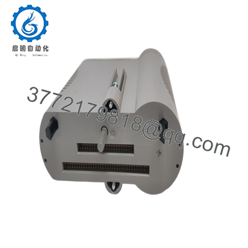
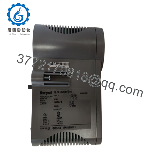
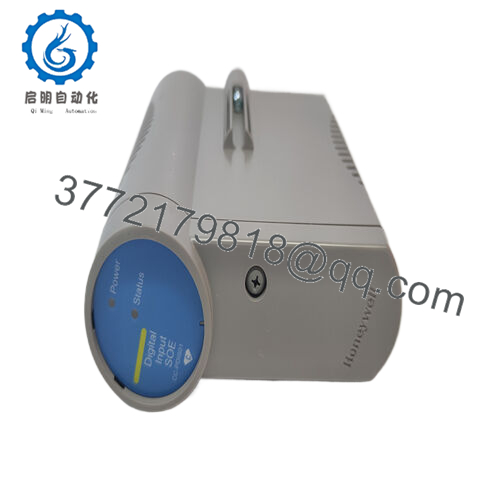
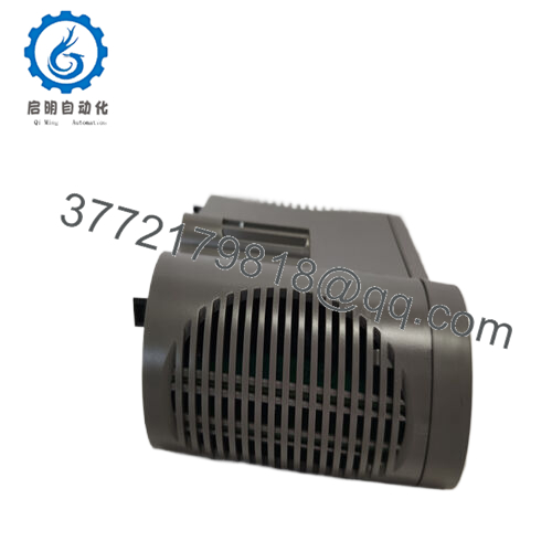
Product Model: CC-PDIS01
Product Brand: Honeywell
Product Series: Series-C / Digital Input (Sequence of Events)
Key Features (from vendor sources):
- Accepts 24 V DC discrete signals and tags inputs with time stamps (SOE = Sequence Of Events) at 1 ms resolution
- Provides 32 input channels for discrete signals
- Offers three operating modes: Normal (20 ms PV scan), SOE mode (1 ms time‐tagging), and Low Latency (5 ms PV scan)
- Includes galvanic isolation (1,500 VAC or ±1,500 VDC) and optical isolation in IOM block

- CC-PDIS01

Main Article
Role & System Fit
In industrial control and automation systems—especially those using Honeywell’s Series-C / C300 / DCS / I/O framework—there is often a requirement not only to read discrete inputs (e.g. on/off switches, sensors) but also to record when those changes occurred. That is the essence of a Sequence of Events (SOE) module. The CC-PDIS01 is a digital input module with SOE capability: it collects 24 V DC discrete signals and logs the exact time (in millisecond resolution) when each input transitions.
Thus it is not just a plain binary input card—it supports time tagging, event sequencing, and integration into logic or historian systems that need precise ordering of events (alarms, interlocks, state changes). This is critical in troubleshooting, safety logging, fault analysis, and compliance environments.
In a system configuration, the CC-PDIS01 sits on the I/O rack/backplane and interacts with the control logic or DCS. Field discrete signals feed into its 32 channels. The module performs time-tagging and passes both the current status (PV / present value) and historical event transitions to higher levels.
Given that Honeywell’s standard digital input module is CC-PDIL01 (Digital Input, 24V)
CC-PDIS01 appears to be the specialized variant with SOE (Sequence of Events) enhancement. Vendor listings confirm this: for CC-PDIS01, QuickTime lists it as “Digital Input SOE 24V Module.” TopBrands PLC gives detailed specs such as scan modes, isolation, and input filtering for CC-PDIS01.MoorePLC describes the module similarly.
Technical Features & Benefits
Here is a closer review of features and operational nuances of CC-PDIS01.
Channels & Input Architecture
- The module supports 32 discrete input channels (32 points) for 24 V DC signals.
- Inputs are isolated via galvanic and optical isolation techniques. CC-PDIS01 supports 1,500 VAC RMS or ±1,500 VDC isolation between input terminals and internal circuits.
- The design uses an input impedance of approximately 4.2 kΩ in its digital input circuits.
Scan Modes & Timing
- Normal Mode: The module scans present value (PV) every 20 ms.
- SOE Mode: When enabled, the module logs input transitions with 1 ms resolution, time-tagging each event while retaining the PV scan rate.
- Low Latency Mode: That mode speeds PV scanning to 5 ms, useful when faster response is needed but full SOE is not required.
- The absolute delay across input filter and isolation is about 5 ms ± 20%.
These multiple modes allow the same module to operate in standard acquisition mode or high-precision logging mode depending on system needs.
Input Thresholds & Signal Levels
- ON sense voltage: Typically ≥ 13 V DC (or ≥ 3 mA) to register as a logical “1.”
- OFF sense voltage: ≤ 5 V DC (or ≤ 1.2 mA) to register as “0.”
- The module supports a DI power voltage range from 18 to 30 V DC for proper operation.
- It can provide non-incendive field power (i.e. safe for hazardous area signaling) in many configurations as part of the I/O block.
Diagnostics & Fault Handling
- Open wire detection is supported (in Normal mode) to detect if wiring is broken or disconnected.
- The module supports redundancy, allowing mirrored input paths or standby modules for critical systems.
- Built-in diagnostic routines monitor data integrity for each channel.
- The module may support external vs internal field power selection, giving flexibility in power sourcing.
Performance & Delay
- The input is filtered and physically isolated, adding a delay of ~5 ms (±20%).
- The response and tagging speed (1 ms resolution) makes it suitable for logging rapid transitions like safety trips, interlock changes, or alarm state sequences.
- The module supports multiple backplane or bus interface standards, integrating with the Series-C / Experion control architecture.
Technical Specifications Table
Below is a compiled spec table for CC-PDIS01, combining vendor data and inferred details. Use it as a reference, verifying with the actual module.
| Specification | Value / Range | |
|---|---|---|
| Model | CC-PDIS01 | |
| Module Type | Digital Input / SOE (Sequence of Events) | |
| Number of Channels | 32 discrete inputs | |
| Power / Input Voltage | 24 V DC (18–30 V range) | |
| ON Sense Threshold | ≥ 13 V DC (or ≥ 3 mA) | |
| OFF Sense Threshold | ≤ 5 V DC (or ≤ 1.2 mA) | |
| Input Impedance | ~ 4.2 kΩ | |
| Isolation | 1,500 VAC RMS or ±1,500 VDC | |
| Modes / Scan Timing | Normal (20 ms PV), SOE Mode (1 ms time-tag), Low Latency (5 ms PV) | |
| Absolute Delay | ~ 5 ms ± 20% | |
| Diagnostic Features | Open wire detection, redundancy support, internal diagnostics | |
| Operating Temperature / Humidity | (Typical industrial range) — vendor data not explicit | |
| Power Consumption | (Not clearly published) |
Again, treat unspecified values as needing confirmation from your hardware or service documentation.
Installation & Maintenance Insights
Here are field tips and guidance when deploying or servicing CC-PDIS01 modules.
Mounting & Rack Integration
- Insert the module while the I/O rack or system is in maintenance or powered-off mode to avoid bus glitches or contact arcing.
- Ensure the backplane connector is fully and cleanly seated; misalignment can cause intermittent faults in SOE logging.
- Leave physical space and access to LED indicator areas or status panels.
Wiring & Signal Layout
- Use shielded twisted-pair wiring for each discrete channel, ideally routed away from power or high-frequency conductors to reduce noise pickup.
- Maintain consistent grounding and shield drain practices to avoid interfering with time-tag accuracy.
- Guarantee wire continuity before energizing; open-wire detection can detect such faults in normal mode but helps to pre-check physically.
Mode Selection & Commissioning
- Choose the appropriate mode at startup: Normal for standard scanning, SOE for logging transitions, or Low Latency for faster scanning.
- After wiring, apply known transitions (e.g. toggle input lines) and verify time‐tagging via the host system or front-end software.
- Confirm diagnostic status bits (e.g. wiring fault, channel errors) during commissioning.
Fault Handling & Replacement
- If a channel behaves erratically, check wiring, shielding, or induced noise rather than immediately replacing the card.
- On replacement or swap, ensure your configuration parameters (mode, thresholds, scaling) are reloaded faithfully.
- Keep a spare CC-PDIS01 or compatible module available—since SOE modules are specialized, lead time may be non-trivial.
Environmental & Reliability Considerations
- Perform periodic checks on connectors and terminal tightness, as vibrational or thermal cycling may loosen connections.
- Watch for signs of electrical stress or corrosion on terminal blocks, especially in harsh environments.
- Consider module-level backups in safety‐critical systems, so that no single module failure results in loss of event logging.
Related / Companion Modules
- CC-PDIL01 — Standard 24 V digital input module (no SOE). Serves as the baseline discrete input module in the series.
- CC-PDIH01 — High-voltage digital input module supporting broader voltage ranges beyond 24 V.
- Other I/O modules in Series-C / C300 — analog input (CC-PAIX01, CC-PAIN01, etc.), analog output, universal I/O (CC-PUIO01), pulse input, etc.
- Digital output modules (PDOB, PDOR) — for driving actuators, relays, etc., complementing the CC-PDIS01 input side in a control loop.


