
 WhatsApp: +86 16626708626
 Email:
  Phone: +86 16626708626
Description
In gas and steam turbine control systems, engineers often grapple with the challenge of reliably driving multiple external relays and solenoid coils while protecting the control logic from inductive kickback and electrical noise common in high-power environments. Unreliable relay actuation can lead to delayed responses in critical sequences—like fuel valve operation, breaker trips, or alarm annunciation—potentially causing turbine trips, reduced availability, or safety concerns. GE DS3800HRDB1C1B addresses this directly as a dedicated relay driver board in the legacy Speedtronic Mark IV turbine control series, providing robust, isolated drive capability for up to dozens of outputs depending on configuration. It’s particularly essential in older installations where the control system must interface with legacy field devices requiring higher current sinking than standard logic outputs can provide. GE DS3800HRDB1C1B incorporates suppression networks to handle inductive loads safely, along with programmable logic via on-board EPROM for custom drive patterns. In industrial automation contexts involving process control and high reliability demands, such as continuous turbine operation, this board ensures consistent signal delivery without overloading upstream I/O cards. For plants maintaining Mark IV systems, GE DS3800HRDB1C1B offers proven durability in harsh conditions, helping avoid costly upgrades while sustaining critical system uptime and minimizing electrical faults that could cascade through the control chain.
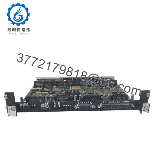
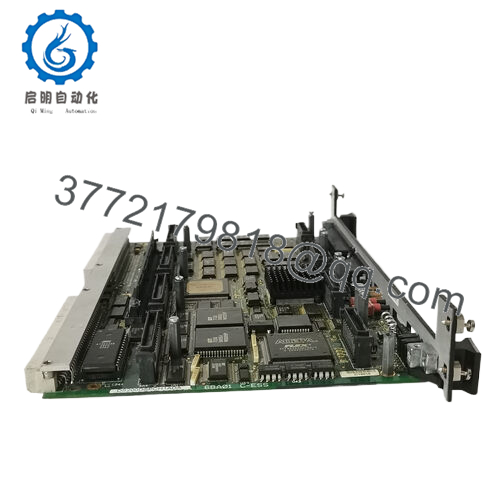
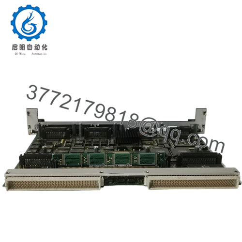
GE DS3800HRDB1C1B functions as an auxiliary output driver within the Mark IV Speedtronic architecture, typically mounted in auxiliary racks or frames alongside core processor and I/O cards. It receives low-level logic signals from the main control cards via ribbon or edge connectors and amplifies them to drive external relays, solenoids, or indicators. The board uses low-side switching to sink current from inductive loads, with built-in suppression (often flyback diodes or snubbers) across output groups to clamp voltage spikes. Multiple edge connectors—one large female port and dual male terminals—allow daisy-chaining or connection to field termination boards. On-board EPROM and EEPROM store configuration data, enabling tailored output behavior without modifying core turbine control software. In the overall system stack, GE DS3800HRDB1C1B sits downstream of the primary digital output cards, extending their capacity for relay-heavy applications like auxiliary interlocks or status indication. It integrates seamlessly with Mark IV’s triple-redundant voting logic, where consistent drive signals contribute to fault-tolerant operation. Diagnostics are limited compared to modern systems but include basic LED status and fuse protection, with faults reported back through the control hierarchy for operator awareness.

- DS3800HRDB1C1B
| Specification | Details |
|---|---|
| Model Number | DS3800HRDB1C1B |
| Brand | General Electric (GE) |
| Type | Relay Driver Board |
| Input Voltage | 24-125 V DC (field side typical) |
| Operating Temp Range | -30 °C to +65 °C (industrial grade) |
| Mounting Style | Rack mount (Mark IV auxiliary frame) |
| Dimensions | Approx. 12 × 9 inches (standard DS3800 form) |
| Weight | Approx. 1.5 kg |
| Interface/Bus | Edge connectors (ribbon/parallel) |
| Compliance | UL, CSA (legacy certifications) |
| Supported Protocols | Proprietary Mark IV signaling |
| Typical Power Draw | 10-15 W (excluding load) |
Selecting GE DS3800HRDB1C1B delivers long-term stability in environments where inductive loads dominate, thanks to its engineered suppression and high-current sinking paths that prevent back-EMF damage to sensitive control electronics. The board’s discrete transistor drivers ensure performance consistency even under frequent cycling, reducing wear on external relays and extending overall system life. Maintenance benefits from straightforward visual inspection—LEDs and accessible fuses allow quick fault isolation without deep diagnostics tools. Because GE DS3800HRDB1C1B is designed for hot insertion in many racks, swapping during outages minimizes downtime. Its programmable memory reduces engineering overhead when adapting to minor sequence changes, avoiding full software revisions. In practice, this translates to fewer nuisance trips from output failures and more predictable behavior in process control loops.
GE DS3800HRDB1C1B excels in power generation facilities operating heavy-duty gas or steam turbines, where it drives relays for breaker control, fuel sequencing, and emergency trips under critical system uptime requirements. Oil and gas upstream sites use it for compressor station interlocks in harsh conditions with vibration and temperature swings. Combined-cycle plants rely on the board for auxiliary system actuation, ensuring fast, reliable responses during load changes or startups.
DS3800HRDB1D1D – Variant with updated revision for improved component sourcing
DS3800HRMA1H1F – Related message announcer interface board
DS3800HRMB1G1D – Higher-density relay interface alternative
DS3800HROA1A1A – Output relay board for direct contact switching
DS3800HPIB1G1E – Parallel interface board often paired for signal distribution
DS3800HMPJ1A1D – Microprocessor jumper board for custom logic
DS3800HVDB1G1D – Voltage distribution board for power routing
DS3800HAFA1D1E – Analog amplifier card for signal conditioning
Prior to installing GE DS3800HRDB1C1B, confirm rack slot compatibility and that edge connectors align with existing cabling—mismatches can stress pins. Verify power supply voltage matches field loads and that suppression networks suit inductive characteristics. Check EPROM programming against the current control configuration to avoid unexpected output states.
For routine maintenance, inspect connectors for corrosion or looseness during annual shutdowns, and cycle outputs manually via test modes to confirm drive strength. Monitor for overheating around high-current transistors during operation. Keep dust clear from ventilation paths. Spares are recommended given the legacy status—reconditioned units often perform reliably after capacitor refurbishment.


