
 WhatsApp: +86 16626708626
 Email:
  Phone: +86 16626708626
Description
In turbine control systems that have been running reliably for decades, few things age as poorly as the original single-channel overspeed trip cards. A cracked solder joint, a drifting frequency-to-voltage converter, or a single faulty magnetic pickup can – and regularly does – force an emergency shutdown. When that happens at 3 a.m. on a 150 MW frame unit, the financial bleed is immediate and brutal.
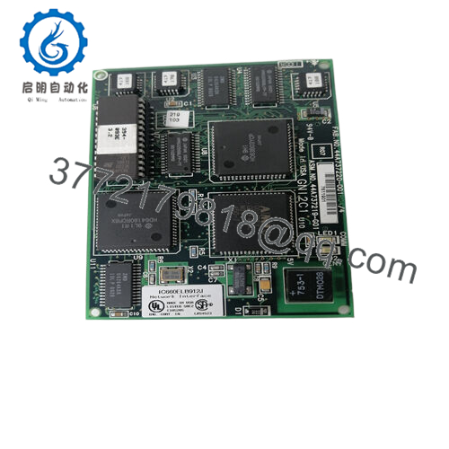
The GE IC3600SOSF1 exists for one reason: to make overspeed protection genuinely fault-tolerant in Mark I and Mark II Speedtronic panels without forcing a costly control-system migration. This triple-redundant, 2-out-of-3 voting overspeed card monitors three independent speed signals in hardware, isolates faults instantly, and only issues a trip command when two or more channels agree that the shaft is truly overspeeding. Plants that have swapped their old single-channel cards for the **GE IC3600SOSF1 routinely report the complete elimination of nuisance trips caused by pickup noise, cable issues, or component drift.
You reach for the GE IC3600SOSF1 when risk assessments flag overspeed protection as a single-point vulnerability, when insurers start asking hard questions about trip reliability, or when you simply refuse to let a $75 component take down a multimillion-dollar machine. It is the drop-in insurance policy that thousands of legacy GE turbines still depend on today.

- IC3600SOSF1
How the Product Works & Fits into a System
The GE IC3600SOSF1 occupies a standard 12-inch card location in the <R> core of any Mark I or Mark II panel. Three isolated frequency inputs (typically from magnetic pickups on the turbine gear) arrive through the normal backplane wiring. Each channel is independently conditioned, squared, and compared against its own front-panel-adjustable setpoint. Voting logic is executed entirely in discrete hardware – no processor, no firmware, no scan cycle – guaranteeing trip times below 20 ms even if the main control CPU is powered off.
A healthy channel shows a green LED; a discrepant or failed channel lights red and is automatically excluded from the vote. The final trip output is a heavy-duty Form-C relay contact pair wired directly into the master trip string (28 VDC or 125 VDC depending on panel vintage). Because the card is completely passive from a software perspective, it satisfies the strict control-versus-protection separation demanded by API-670 and most corporate loss-prevention standards.
Installation is literally a five-minute job: remove the old card, insert the GE IC3600SOSF1, set the three multi-turn pots to the desired trip points, and walk away. No rewiring, no new termination points, no logic changes.
| Specification | Details |
|---|---|
| Model Number | IC3600SOSF1 |
| Brand | GE Energy |
| Type | Triple-redundant overspeed trip module |
| Input Voltage | 28 VDC ±10 % (from panel regulated supply) |
| Operating Temp Range | –10 °C to +65 °C continuous |
| Mounting Style | Mark I / Mark II card file (44-pin edge) |
| Dimensions | 12.25 in × 8.5 in × 1.5 in |
| Weight | 0.95 kg |
| Interface/Bus | Direct backplane, no fieldbus |
| Compliance | API-670, IEEE-279 compliant design |
| Supported Protocols | Raw frequency only (5–10 000 Hz typical) |
| Typical Power Draw | 4.8 W at 28 VDC |
Real-World Benefits
With the GE IC3600SOSF1 in the rack, a single bad pickup or a lightning-induced transient no longer costs you a forced outage. The hardware 2-out-of-3 vote has proven itself for decades in some of the harshest environments on the planet – offshore platforms in the North Sea, desert compressor stations, and refineries running 8000-hour campaigns. One Gulf Coast plant I supported calculated that three avoided false trips in a single year paid for upgrading every turbine on site.
Technicians love the self-diagnostic LEDs and the fact that a failed channel never forces a shutdown – you can replace the card at the next convenient time rather than in the middle of the night. The setpoint pots are 25-turn and extremely temperature-stable, so calibrations hold for many years unless someone deliberately moves them. In short, the GE IC3600SOSF1 turns what used to be a chronic weak spot into a genuinely “set and forget” protection layer.
Typical Use Cases
The GE IC3600SOSF1 is still the go-to solution on Frame 3, 5, 6, and 7 gas turbines running Mark I or Mark II controls in base-load power plants, on mechanical-drive units in pipeline service, and on steam turbines in pulp-and-paper or sugar mills, and even on some hydro units that inherited Speedtronic exciter panels. Anywhere continuous operation is measured in years rather than hours and where a spurious trip is measured in hundreds of thousands of dollars, this card remains in active service.
Compatible or Alternative Products
IC3600SOSD1 – Original single-channel card (direct predecessor)
IC3600SOSE1 – Triple card with wider frequency range for high-speed machines
IC3600SOSG1 – Adds front-panel test pushbuttons and alarm contact
IC3600STKH1 – Thermocouple overspeed card sometimes used in parallel
IC3600EPSN3 – Companion 28 VDC power supply module
IC3600LIBA1 – Input buffer board for remote pickups
IC3600AVIA1 – Voltage isolator when mixing 28/125 VDC panels
DS3820OPTC – Third-party upgraded replacement with modern components
Setup Notes & Maintenance Insights
Confirm that your panel is delivering clean 28 VDC ±2 V to the card edge before insertion – ripple or sags will cause erratic LED behavior. Verify pickup wiring lands on the correct backplane pins (usually 25/26, 29/30, 33/34). Leave an empty slot on at least one side for airflow; the card dissipates about 5 W and Mark II racks are notoriously tight on cooling.
During commissioning, inject a calibrated frequency source or spin the shaft with the starter to set each pot roughly 8–12 % above max continuous speed. Record the exact counts on the card label. In operation, glance at the three green LEDs during every shift walkdown. A steady red LED means that channel is out of the vote – plan a replacement within the next 30 days, but you can continue running safely on the remaining two. Perform a full functional test during every major outage using a frequency generator; the relay contacts should drop within one cycle of crossing setpoint.


