
 WhatsApp: +86 16626708626
 Email:
  Phone: +86 16626708626
Description
Key Technical Specifications
| Parameter | Value |
| Manufacturer | H.M. Stein Sohn (Germany) |
| Part Number | E235.1 |
| Relay Count | 10 Channels (Standard Configuration) |
| Coil Voltage | 24 V DC |
| Contact Rating | 250 V AC / 2 A (Resistive Load) |
| Form Factor | Eurocard 100mm x 160mm |
| Connector Type | DIN 41612 (Type F or H) |
| Switching Time | < 15 ms |
| Indication | On-board Status LEDs (Per Channel) |
| Mounting | 19″ Rack / Sub-rack System |
Product Introduction
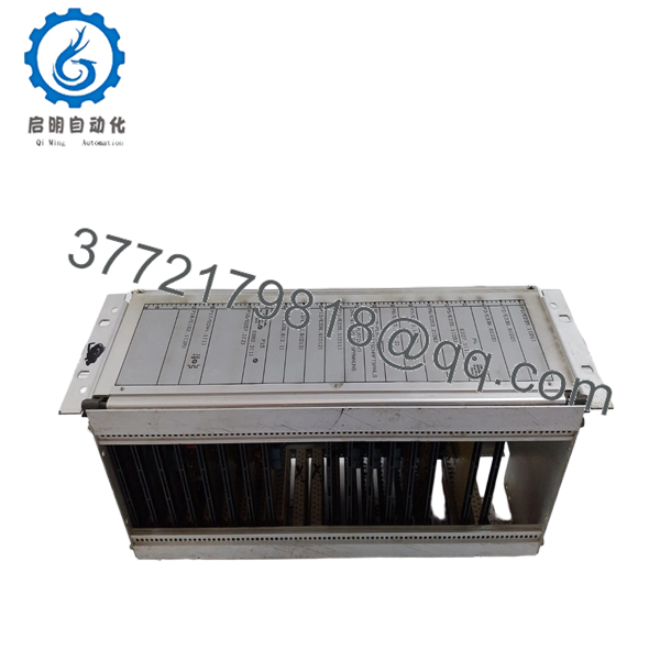
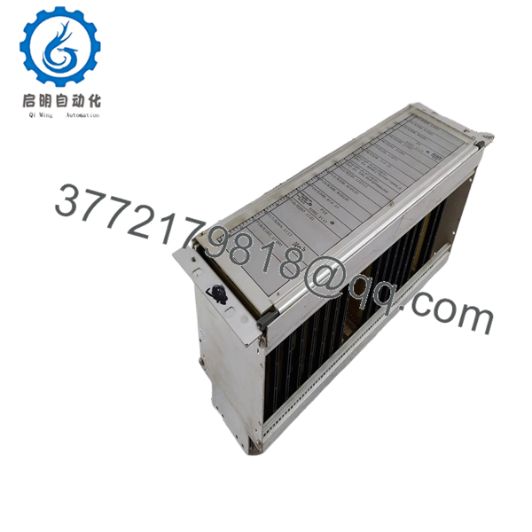
The H.M. Stein Sohn E235.1 is a robust relay interface module designed for signal distribution and isolation in legacy maritime automation systems. It typically serves as the “output” layer for alarm monitoring systems (AMS) or emergency shutdown (ESD) logic, providing dry-contact outputs to trigger external sirens, fuel valves, or ventilation dampers.
Engineered for the high-vibration and saline environments of shipboard engine rooms, the E235.1 features high-quality electromagnetic relays with superior contact reliability. As an obsolete component, it is a critical spare for maintaining the functional safety of older vessel control consoles where modern PLC I/O cannot be easily integrated without extensive rewiring.
- E235.1
- E235.1
Installation & Configuration Guide
Stage 1: Pre-Installation Preparation (Estimated Time: 10 mins)
- ⚠️ Safety First: Notify the bridge or engineering watch. Be aware that pulling this board may trigger a “System Fault” or inadvertently drop out safety interlocks. Ensure critical machinery is in “Local” control.
- Tools Required: ESD wrist strap, small flat-head screwdriver, and a multimeter.
- Data Backup: Document which relays are energized during normal operation by observing the on-board LEDs on the old card before powering down.
Stage 2: Removing the Old Module
- Wear a grounded ESD strap to protect the coil-driver transistors on the PCB.
- If the module is secured by faceplate screws, loosen them completely.
- Pull the E235.1 straight out using the card ejectors. Warning: Do not touch the gold edge-connector pins with your bare fingers, as skin oils cause oxidation over time.
- Check the rack’s female connector for any charred pins—a common sign of over-current on a previous relay channel.
Stage 3: Installing the New E235.1
- Visual Match: Ensure the revision number (E235.1) matches exactly. Earlier versions (E235.0) may have different pinouts for the common return.
- Slide the PCB into the rack guides.
- Push firmly until the board “seats” into the backplane. You should feel the pins engage.
- Secure the faceplate screws. This is vital in marine applications to prevent the board from vibrating out of the socket.
- Self-Checklist: [ ] Connector aligned, [ ] Firmly seated, [ ] Screws secured.
Stage 4: Power-On & Testing (Estimated Time: 15 mins)
- Restore 24V DC power to the system.
- Observe the status LEDs. They should match the pattern recorded in Stage 1.
- Loop Test: Force a non-critical alarm at the control station to verify the corresponding relay on the E235.1 clicks and the LED illuminates.
- ⚠️ Troubleshooting Note: If a relay clicks but the external device doesn’t activate, check the external fuse for that specific output loop; the relay contacts are protected, but the field wiring usually is not.
Frequently Asked Questions (FAQ)
Can I replace the individual relays on the E235.1 board?
Technically, yes, if you are skilled in through-hole soldering. However, in a marine environment, the heat from desoldering can weaken the PCB traces. For mission-critical systems (like fire or fuel shutoff), replacing the entire board with a verified New Surplus unit is the only way to ensure certified reliability.
What is the life expectancy of the E235.1?
The mechanical life of the relays is typically 10 million cycles, but in marine environments, the contacts usually fail due to “pitting” from inductive loads or oxidation. If your board is over 15 years old, the capacitors driving the coils are also likely reaching their end-of-life.
Are the contacts on this board “Dry” (Volt-Free)?
Yes, in the standard E235.1 configuration, the relay contacts are isolated from the 24V DC internal logic. This allows you to switch different voltages (e.g., 110V AC for a siren and 24V DC for a solenoid) on the same board.
Why is my “Power” LED on, but none of the relays are firing?
Check the common return line (COM). If the logic-side ground is interrupted, the transistors cannot sink current to fire the coils. Verify the backplane voltage at the connector pins using a multimeter.
Is this board compatible with salt-mist environments?
Stein Sohn boards from this era were designed for marine use, often featuring a conformal coating. However, because these are legacy parts, we recommend ensuring your control cabinet’s humidity control (heaters) is functional to prevent condensation on the logic traces.


