
 WhatsApp: +86 16626708626
 Email:
  Phone: +86 16626708626
Description
3. Key Technical Specifications
- Application: Legacy industrial control systems (power, transport, infrastructure)
- Board Type: Plug-in control / interface PCB
- Functionality: Signal processing, I/O interfacing, or subsystem control
- Backplane Interface: Proprietary rack-based connection
- Power Supply: Chassis-fed (commonly 24 V DC or system bus dependent)
- I/O Type: Digital/analog interface (variant dependent)
- Revision: Issue 5 (hardware revision control)
- Operating Temperature: 0 to +50 °C (typical control room environment)
- Mounting: Rack or cabinet-mounted system
- Compliance: Industrial control standards (project-specific)
4. Product Introduction
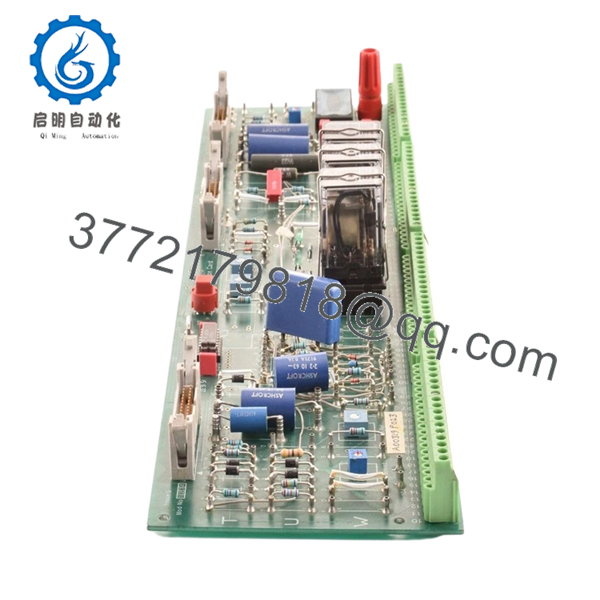
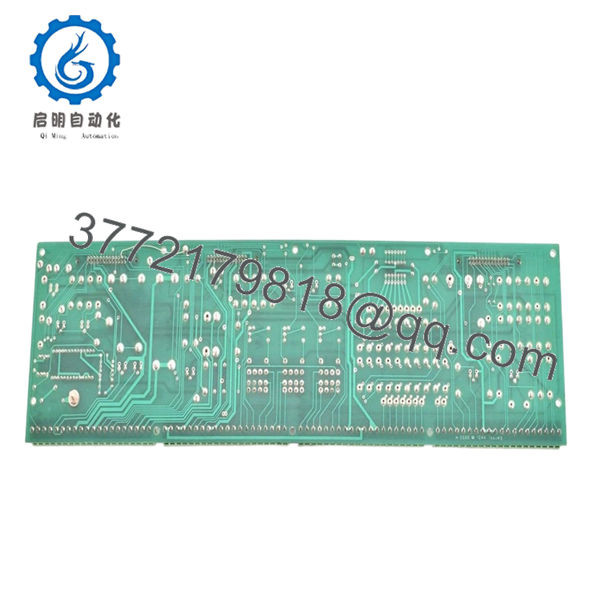
Harland Simon H 2668 M 1244 Issue 5 is a legacy industrial control PCB used in custom or semi-standard control systems, commonly found in power generation, rail, or infrastructure automation environments. These systems are typically engineered-to-order rather than mass-produced platforms.
In field experience, boards like this are tightly integrated into site-specific control architectures. Replacement is usually driven by failure rather than upgrade, since migrating away from these systems often requires full redesign, including I/O mapping and control logic revalidation.
5. Installation & Configuration Guide
Stage 1: Pre-Installation Preparation (Estimated: 20 minutes)
- ⚠️ Safety First: Confirm system is in safe state. Lock out power sources. These systems often control critical infrastructure — coordinate with operations.
- Tools Required: ESD strap, multimeter, labeling tags, screwdriver, smartphone.
- Data Backup:
- Document wiring and terminal layout (photos mandatory)
- Record system status and alarms
- Capture any configurable jumpers or DIP switch settings
Stage 2: Removing the Old Module (Estimated: 10–15 minutes)
- Identify exact board position in rack.
- Label all connected wiring and interfaces.
- Disconnect carefully — do not force terminals.
- Release retaining clips or screws.
- Pull board straight out along guides.
- ⚠️ Note: Keep the original board nearby — you may need it for jumper reference.
Stage 3: Installing the New Module (Estimated: 15 minutes)
- Apply ESD protection. Verify model H2668 M1244 Issue 5 exactly matches.
- Compare jumper/DIP configuration with old board.
- Insert along guide rails evenly.
- Secure with clips or mounting screws.
- Reconnect wiring based on labeled references.
- Self-Checklist:
- Model and Issue match
- Jumpers/DIPs replicated
- Wiring correctly reconnected
- Board securely mounted
Stage 4: Power-On & Testing (Estimated: 20–30 minutes)
- Pre-Power Check: Use multimeter to verify no shorts on supply rails.
- Power-On Steps:
- Restore power to system.
- Observe system indicators and alarms.
- Verify module recognition (if monitored).
- Test associated I/O signals.
- Confirm system returns to normal operation.
- ⚠️ Troubleshooting Note:
- No response → jumper/DIP mismatch
- Incorrect signals → wiring error or pinout difference
- Intermittent faults → poor backplane contact
6. Frequently Asked Questions (FAQ)
Q1: Is this a standard PLC module or a custom board?
This is typically part of a custom or semi-custom control system. Harland Simon systems are often engineered for specific projects, not standardized like Siemens or ABB PLCs.
Q2: Is Issue 5 interchangeable with earlier issues?
❗ Not guaranteed.
Different issue levels may have:
- Component changes
- Timing differences
- Modified I/O behavior
I’ve seen systems behave unpredictably when mixing revisions.
Q3: Can I upgrade this system to a modern PLC?
Not directly. This would require:
- Full I/O remapping
- Control logic rewrite
- Panel redesign
This is a migration project, not a replacement task.
Q4: Why is documentation so limited?
These systems were often delivered as project-specific solutions. Documentation is usually site-held, not publicly available.
Q5: What’s the biggest risk during replacement?
❗ Miswiring or jumper mismatch.
I’ve seen engineers install the correct board but forget a single jumper — system behavior was completely wrong.
Q6: Why is pricing inconsistent?
Supply is extremely limited:
- Decommissioned systems
- Spare parts from legacy projects
Condition varies — always request test evidence.
Q7: Can this fail due to age even if unused?
Yes. Electrolytic capacitors and solder joints degrade over time. Even unused boards should be tested before deployment.

- H 2668 M 1244
- H 2668 M 1244
SOP Quality Transparency (Inspection & Testing Process)
1. Inbound Inspection & Traceability
- Verified model: H2668 M1244 Issue 5
- Serial and PCB markings checked
- Visual inspection under magnification (no corrosion, no rework marks)
- Connector and solder joint inspection
2. Live Functional Testing
- Tested in a compatible rack or simulated environment (where available)
- Power-on behavior verified
- Signal I/O simulation performed (where possible)
- 24-hour continuous operation test
- Test report generated (available upon request)
3. Electrical Parameter Testing
- Insulation resistance >10 MΩ @ 500 V
- Ground continuity verified
- Power rail stability checked using Fluke 115
4. Firmware & Configuration Verification
- Hardware revision confirmed (Issue 5)
- Jumper/DIP configuration documented
- Photographic records maintained
5. Final QC & Packaging
- QC sign-off with traceability
- ESD-safe sealed packaging
- Shock-protected industrial carton
- QC Passed label with inspection date
Test photos and videos available upon request.
Technical Pitfall & Survival Guide
1. Revision (Issue) Mismatch
❗ This is the biggest trap.
I’ve seen Issue 3 replaced with Issue 5 — system partially worked, but timing errors caused intermittent faults.
Avoidance: Match Issue number exactly whenever possible.
2. Jumper / DIP Switch Errors
❗ Most common field mistake.
One incorrect jumper can alter signal routing.
Avoidance: Take clear photos before removal and replicate exactly.
3. Wiring Misidentification
❗ Especially in older panels with faded labels.
I’ve seen swapped wires cause incorrect outputs.
Avoidance: Label everything before disconnecting.
4. Power Supply Variations
Older systems may have unstable rails.
Avoidance: Verify voltage levels before installing new board.
5. ESD Damage
❗ Older PCBs are more sensitive.
Static can cause latent failures.
Avoidance: Always use grounded wrist strap.


