
 WhatsApp: +86 16626708626
 Email:
  Phone: +86 16626708626
Description
3. Key Technical Specifications
- Application: Industrial control systems (power, rail, infrastructure)
- Board Type: Plug-in control / interface PCB
- Functionality: Signal conditioning, control logic, subsystem interface
- Backplane Interface: Proprietary rack connection
- Power Supply: System-fed (commonly 24 V DC or ±15 V rails depending on design)
- I/O Type: Mixed digital/analog (project-specific wiring)
- Connector Type: Edge connector / terminal interface
- Operating Temperature: 0 to +50 °C typical
- Mounting: Rack or cabinet-based system
- Revision Identifier: P1385
4. Product Introduction
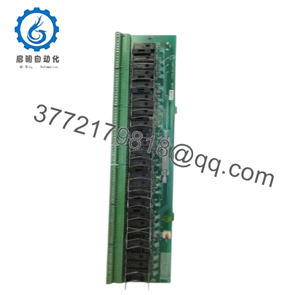
Harland Simon H4890P1385 is a legacy control PCB used in engineered industrial control systems, typically deployed in infrastructure environments such as power generation, transport, and specialized automation installations. These systems are usually custom-built, not based on standardized PLC platforms.
In practice, this board functions as part of a tightly integrated control chain. Replacement requires strict adherence to the original configuration, including wiring, jumper settings, and revision matching. Most issues arise from configuration mismatches rather than hardware defects.

- H4890P1385
5. Installation & Configuration Guide
Stage 1: Pre-Installation Preparation (Estimated: 20 minutes)
- ⚠️ Safety First: Ensure system is in a safe state. Lock out/tag out all power sources and confirm outputs are de-energized.
- Tools Required: ESD strap, multimeter, screwdriver, labeling tags, smartphone for documentation.
- Data Backup:
- Photograph all wiring and terminal connections
- Record system alarms and operational status
- Capture jumper/DIP switch configurations
Stage 2: Removing the Old Module (Estimated: 10–15 minutes)
- Identify board location within rack.
- Label all wiring clearly — do not rely on memory.
- Disconnect wiring carefully to avoid terminal damage.
- Release retaining clips or screws.
- Pull board straight out along guide rails.
- ⚠️ Note: Retain original board for configuration reference.
Stage 3: Installing the New Module (Estimated: 15 minutes)
- Apply ESD protection. Confirm model H4890P1385 exactly matches.
- Replicate all jumper/DIP settings from the original board.
- Insert board evenly into rack guides.
- Secure with mounting hardware.
- Reconnect wiring using labels and photos.
- Self-Checklist:
- Full model match
- Jumper/DIP settings replicated
- Wiring restored correctly
- Board securely mounted
Stage 4: Power-On & Testing (Estimated: 20–30 minutes)
- Pre-Power Check: Verify no short circuits on supply rails using a multimeter.
- Power-On Steps:
- Restore system power.
- Observe system indicators and alarms.
- Verify module response.
- Test associated I/O signals.
- Confirm stable system operation.
- ⚠️ Troubleshooting Note:
- No response → incorrect jumper settings or wrong revision
- Incorrect outputs → wiring mismatch
- Intermittent faults → backplane connection issues
6. Frequently Asked Questions (FAQ)
Q1: Is H4890P1385 interchangeable with other H4890 variants?
❗ No.
The P1385 suffix defines the exact configuration. Even minor differences can affect system behavior.
Q2: Is this a standard PLC module?
No. This is part of a custom-engineered control system, not a modular PLC under IEC 61131 standards.
Q3: Can this system be upgraded to a modern PLC?
Only through a full migration project:
- I/O remapping
- Control logic redevelopment
- Panel redesign
Q4: Why is documentation limited?
These systems were delivered as project-specific solutions. Documentation is usually retained on-site or by the original integrator.
Q5: What is the biggest installation risk?
❗ Configuration mismatch.
Incorrect jumper settings or wiring errors are the most common causes of failure.
Q6: Why does pricing vary widely?
Supply is limited:
- Decommissioned systems
- Spare inventory
Condition varies — always request testing evidence.
Q7: Can unused boards fail over time?
Yes. Component aging (especially capacitors and solder joints) can lead to failure even if unused.
SOP Quality Transparency (Inspection & Testing Process)
1. Inbound Inspection & Traceability
- Verified model: H4890P1385
- PCB identifiers and markings checked
- Visual inspection under magnification (no corrosion, no rework marks)
- Connector integrity verified
2. Live Functional Testing
- Tested in compatible rack or simulated environment (if available)
- Power-on behavior verified
- Signal I/O simulation performed where possible
- 24-hour continuous operation test
- Test report generated (available upon request)
3. Electrical Parameter Testing
- Insulation resistance >10 MΩ @ 500 V Megger
- Ground continuity verified
- Power rail stability measured using Fluke 115 multimeter
4. Firmware & Configuration Verification
- Revision P1385 confirmed
- Jumper/DIP configurations documented
- Photographic records maintained
5. Final QC & Packaging
- QC sign-off with traceability
- ESD-safe sealed packaging
- Shock-protected industrial carton
- QC Passed label with inspection date
Test photos and videos available upon request.
Technical Pitfall & Survival Guide
1. Part Number Mismatch
❗ Most common issue.
H4890 looks correct, but wrong suffix — system behaves incorrectly.
Avoidance: Always match full model including P1385.
2. Jumper / DIP Switch Misconfiguration
❗ Happens constantly.
One incorrect setting can alter signal paths or logic behavior.
Avoidance: Photograph and replicate exactly.
3. Wiring Errors
❗ Especially in older panels with poor labeling.
Miswiring leads to incorrect outputs or system faults.
Avoidance: Label everything before disconnecting.
4. Power Supply Instability
Older systems often have degraded power rails.
Avoidance: Verify voltage levels before installing replacement.
5. ESD Damage
❗ Silent failure risk.
Board may pass initial checks but fail under load.
Avoidance: Use grounded wrist strap and ESD-safe workspace.


