
 WhatsApp: +86 16626708626
 Email:
  Phone: +86 16626708626
Description
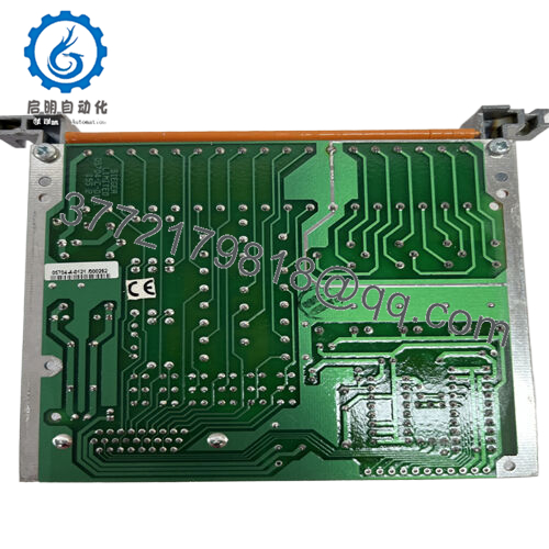
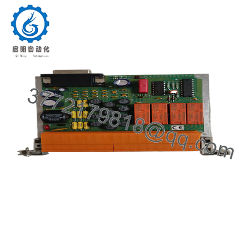
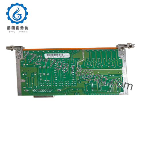
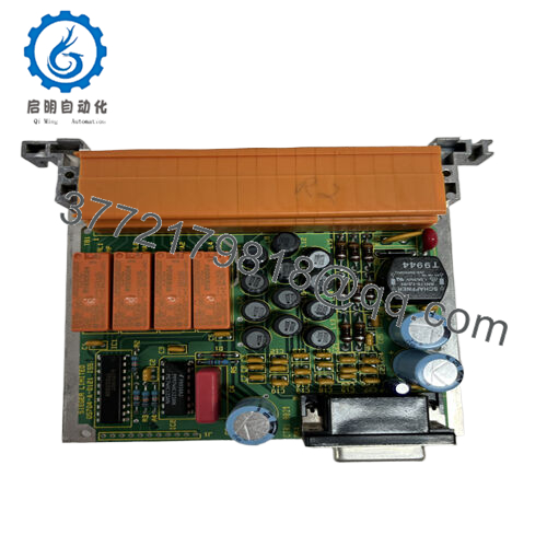
Product Model: 05704-A-0121
Product Brand: Honeywell / Zellweger / Honeywell Analytics
Product Series: System 57 / 5704 Relay Interface Modules
Key Features:
- Provides 4 SPCO (single pole changeover) relays for alarm output and interface to external circuits.
- Relay operation is selectable: latching or non-latching, energized or de-energized modes.
- Relay contact rating: 5 A @ 110/250 V AC (non-inductive) or 5 A @ 32 V DC (non-inductive)
- Low power consumption: typical ~1 W, maximum ~1.7 W
Main Article
Role & System Context
In Honeywell’s System 57 / 5704 family of fire, gas, and process safety systems, control and relay cards are modular components building the logic, sensor interface, alarm, and output functions. The 05704-A-0121 is a Quad Relay Interface Card, meaning its principal role is to provide alarm relay outputs from the 5704 rack to external devices (sirens, shutdown valves, indicator panels, etc.).
When a control card detects a threshold breach or fault, it signals the relay interface card to actuate one or more relays, which then drive physical outputs. The 05704-A-0121 sits between the control logic and external wiring, enabling clean separation and modular replacement.
Vendor listings refer to it as “Quad Relay Interface Card – 5704 (4 SPCO relays).” It is used in System 57 racks as the output relay module for up to four channels, matching control cards and allowing for scalable alarm output implementations.
Because the 5704 and 5704F series are commonly used in safety, gas detection, and fire systems, having a reliable relay interface card is essential. The modular design allows you to swap or upgrade relay cards independently of the control logic or sensor interfaces.
Technical Features & Benefits
Relay Configuration & Flexibility
The 05704-A-0121 comes with 4 SPCO relays (single-pole changeover). Each relay can be configured in multiple ways:
- Latching or non-latching — you can choose whether the relay remains in the triggered position until reset (latch) or returns when fault clears (non-latch).
- Energized or de-energized logic — configurable depending on fail-safe requirements.
This flexibility helps tailor the relay behavior to site needs (e.g. normally closed alarms, fail-safe energized outputs).
Contact Ratings & Load
The relay contacts are rated:
- 5 A at 110/250 V AC (non-inductive)
- 5 A at 32 V DC (non-inductive)
These ratings are sufficient for most control panels, warning devices, and modest loads. For inductive loads (coils, motors), appropriate derating or snubbing should be used.
Power & Efficiency
The module’s power draw is low:
- Typical: ~1 W
- Maximum: ~1.7 W
This low consumption means it adds minimal thermal load to the rack and allows more modules per power budget.
Physical & Wiring Details
- Dimensions: 132 mm height × 25 mm width × 119 mm depth
- Weight: ~230 g
- Field terminal wiring supports up to 14 AWG (2.5 mm²) conductors
- Relay interface board serves as the hardware interface between the 5704 control cards and external wiring.
Alarm Logic Support
The card interfaces closely with control cards, responding to alarm conditions and providing relay output in coordination with system logic. Because the relay behavior is configurable, you can adapt to different alarm schemes (e.g. latching, timed, disable, reset) depending on the process or standard.
This modular separation (control vs. relay) also aids in maintenance: if a relay fails, you don’t need to disturb sensor or control modules — swap the relay interface card.

- 05704-A-0121

Technical Specifications Table
| Specification | Value / Range | |
|---|---|---|
| Model | 05704-A-0121 | |
| Type | Quad Relay Interface Card | |
| Number of Relays | 4 SPCO | |
| Relay Configurations | Latching / non-latching, energized / de-energized | |
| Contact Ratings | 5 A @ 110/250 V AC; 5 A @ 32 V DC (non-inductive) | |
| Power Consumption | Typical ~1 W; Max ~1.7 W | |
| Dimensions | 132 mm × 25 mm × 119 mm | |
| Weight | ~230 g | |
| Wire Terminal | Up to 2.5 mm² (14 AWG) | |
| Role | Interface between control cards and external circuits | |
| Application | Fire/gas control, alarm outputs, safety systems |
Installation & Maintenance Insights
Here are some field-tested tips to ensure reliable performance and maintainability.
Mounting & Rack Insertion
- Insert the card only when the 5704 rack is unpowered or in maintenance mode to avoid contact arcing or logic errors.
- Ensure correct alignment and full seating in the backplane connector.
- Keep the relay interface card easily accessible for replacement or service — do not bury it behind densely packed modules.
Wiring & Field Terminals
- Use proper rated conductors (up to 14 AWG / 2.5 mm²) with ferrules or insulated ends to avoid stray strands shorting adjacent terminals.
- Route wiring away from high-voltage lines or inductive loads to reduce cross-talk or interference.
- Use snubbers or suppression (RC networks, diodes) when driving inductive coils to reduce relay contact wear.
Relay Use & Testing
- Exercise relays periodically (in maintenance mode) to verify operation and avoid contact sticking.
- Test both latching and non-latching configurations (if used) and verify that resets or latch releases behave correctly.
- Monitor for contact heating or wear, especially on DC inductive loads — replace the card if contacts show erosion or excessive resistance.
Spare Planning & Replacement
- Keep at least one replacement 05704-A-0121 (or equivalent) in inventory, particularly in critical alarm systems.
- When replacing, match the same revision or firmware (if applicable) to ensure compatibility with control cards.
- Before installing a spare, bench-test relays with dummy loads to confirm all channels function as expected.
Compatibility & Upgrades
- Because the 5704 control system supports mixing control cards and relay cards in the same rack, the interface may coexist with SMART control cards, gas control cards, or fire logic modules.
- For upgraded systems or migration to 5704F or future architectures, you may need to confirm backplane and signaling compatibility.
Related Modules / System Cards
Some sibling or complementary modules used with 05704-A-0121 are:
- 05704-A-0144 – Four-Channel Control Card (catalytic input) that provides sensor interface and logic, which pairs with relay interface cards like 0121.
- 05704-A-0131 – Alternative Relay Interface Assembly variant (quad relay module) that may have variant features over 0121.
- Engineering / Setup Cards (e.g. 05701-A-0361) – used to program, configure, and calibrate 5704 system, including relay behavior.
- Analog I/O / Control Cards – for cases where logic or sensor input rather than relay output is needed, in the same 5704 rack.
These cards share the same mechanical format, backplane connectors, and system logic interdependencies.


