
 WhatsApp: +86 16626708626
 Email:
  Phone: +86 16626708626
Description
3. Key Technical Specifications
| Parameter | Value |
| Component Type | Main Processor / Signal Interface Board |
| System Compatibility | VisionMaster FT Radar / ECDIS Units |
| Logic Voltage | +5 V DC, +12 V DC, -12 V DC (System Supplied) |
| Interface Ports | Dual Ethernet, RS-422, NMEA 0183 |
| Firmware Slot | On-board EPROM / Flash Socket |
| Form Factor | Proprietary Sperry Marine Rack/Chassis Mount |
| Operating Temp | -15 to +55 °C (IEC 60945 compliant) |
| Vibration Rating | Marine Grade (High-G maritime shock certified) |
4. Product Introduction
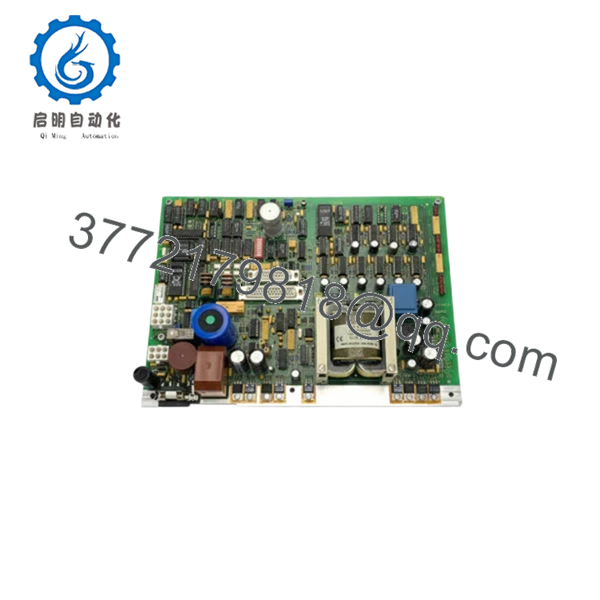
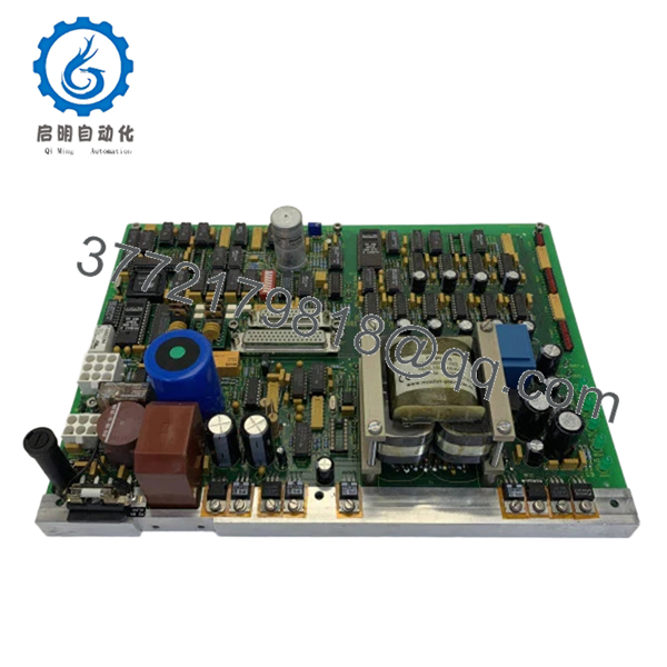
The Sperry Marine 029798-0000-005 is a high-performance processor board serving as the backbone for the VisionMaster FT radar and navigation series. This PCBA manages the complex task of processing raw radar video signals, overlaying ARPA targets, and coordinating data communication between the bridge workstation and the transceiver aloft.
Engineers rely on the 029798-0000-005 for its exceptional processing stability during high-density traffic scenarios. It is designed to meet stringent IMO and IEC standards for Type Approved navigation equipment. Replacing a degraded board with this genuine Sperry assembly restores the critical timing required for accurate target tracking and eliminates the “system freeze” issues common with aging electrolytic capacitors on legacy boards.

- 029798-0000-005
- 029798-0000-005
5. Installation & Configuration Guide
Stage 1: Pre-Installation Preparation (Estimated Time: 15 mins)
- ⚠️ Safety First: Power down the VisionMaster workstation and the Radar Transceiver (Scanner). High-voltage pulses from the radar can backfeed into the processor during hot-swapping.
- Tools Required: PH1 and PH2 screwdrivers, ESD grounding mat/strap, and a vacuum/canned air (for cleaning the chassis).
- Data Backup: If the system is still bootable, export the Radar Setup configuration (Antenna height, blind sectors, and heading alignment) to a USB drive.
Stage 2: Removing the Old PCBA
- Open the VisionMaster FT processor cabinet or pedestal.
- Disconnect all ribbon cables and serial headers. ⚠️ Warning: Do not pull by the wires; use the plastic ejector tabs.
- Unscrew the retaining standoffs.
- Carefully slide the 029798-0000-005 out of its guide rails. Inspect the motherboard/backplane pins for any signs of bending or oxidation.
Stage 3: Installing the New Board (Estimated Time: 20 mins)
- ESD Prep: This board is highly sensitive to static. Wear a grounded strap and handle the board only by the edges.
- Jumper Matching: Check the revision 005 against your old board. Ensure any physical jumpers (e.g., for COM port termination or ID settings) are moved to the identical positions on the new board.
- Seating: Align the board with the card guides and push firmly until the connectors are fully seated.
- Wiring: Reconnect the ribbon cables. Check that the locking clips “click” into place.
- Self-Checklist: [ ] Jumpers verified, [ ] Stand-offs tight, [ ] Cables seated.
Stage 4: Power-On & Commissioning
- Power up the workstation.
- BIOS/Firmware Check: During boot, verify the board is recognized by the system software. You may need to re-flash the specific firmware version used by your vessel’s software build.
- Heading Alignment: After the radar stabilizes, check the Heading Marker alignment against the ship’s gyro. Perform a “Radar Setup” recalibration to ensure targets appear at the correct range and bearing.
- ⚠️ Troubleshooting: If the “Radar Video Fail” alarm persists, check the connection between this board and the Signal Converter card.
6. Frequently Asked Questions (FAQ)
Q: Can I use 029798-0000-005 to replace an older revision like -001 or -002?
A: In most VisionMaster FT systems, the -005 is backward compatible as it represents a later hardware revision with improved thermal management. However, you MUST verify that your current software version supports the updated chipset. If your software is more than 10 years old, a patch may be required.
Q: Is this board “Plug and Play”?
A: Not entirely. While the hardware is a direct fit, navigation parameters (heading offset, tune settings, and sector blanks) are stored in the system memory. You will need to enter the service menu to re-input these values once the new board is detected.
Q: Why is my system failing to track targets (ARPA) after swapping the board?
A: This is usually a firmware mismatch or a configuration error in the “Target Processing” menu. Ensure the CPU on the 029798 board is communicating correctly with the tracking coprocessor. If the hardware is healthy, a simple “Restore Factory Defaults” followed by a manual setup often fixes this.
Q: Is this a refurbished or repaired board?
A: No. This is New Original (New Surplus) stock. For critical navigation equipment like a SOLAS-mandated radar, we do not recommend repaired boards due to the risk of “latent defects” in the multi-layer PCB.
Q: Will this board fix the “Disk Boot Failure” error?
A: Probably not. “Disk Boot Failure” usually points to a failing Hard Drive (HDD) or Solid State Drive (SSD). However, if the board’s on-board SATA/IDE controller has failed, it can cause the same symptom. Check the drive on a separate PC first; if the drive is good, then this processor board is the culprit.


