
 WhatsApp: +86 16626708626
 Email:
  Phone: +86 16626708626
Description
3. Key Technical Specifications
| Parameter | Value |
|---|---|
| System Compatibility | Navigat X Mk1 gyrocompass |
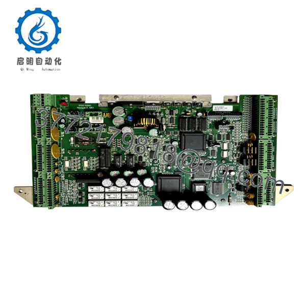
| Board Type | Main control board (masterboard) |
| Revision | Rev H / Rev CA (verify before purchase) |
| Input/Output Voltages | 11 V, 24 V, 100 V, multi-rail outputs |
| Frequency Output | 333 Hz (dual 15 V rails) |
| Connector Type | Multi-pin backplane + terminal interface |
| Weight | ~2.3–2.45 kg |
| Dimensions | ~245 × 230 × 30 mm |
| Application | Marine navigation / gyrocompass processing |
| Lifecycle Status | Discontinued / legacy system |
| Typical Condition | New surplus / used / refurbished |
4. Product Introduction
The Sperry Marine 2133.10300 is a main control board used in the Navigat X Mk1 gyrocompass system. It handles signal processing, power distribution, and internal control logic for marine navigation platforms.
In real vessel retrofits, this board acts as the central processing layer between sensor inputs and heading output systems. Because it is tightly coupled to the Navigat X Mk1 architecture, engineers typically source the exact revision (e.g., Rev H) to avoid system boot or calibration issues. Availability today is mostly through surplus or refurbishment channels.
5. Installation & Configuration Guide
Stage 1: Pre-Installation Preparation (Estimated: 10–15 minutes)
- ⚠️ Safety First:
Inform bridge crew. Power down gyrocompass system. Lock out supply. Wait 5 minutes for discharge. - Tools Required:
ESD strap, PH1 screwdriver, multimeter (Fluke 115 class), labeling tape, smartphone - Data Backup:
- Record system parameters (heading offsets, calibration values)
- Photograph all connectors and board position
- Document revision number (Rev H vs Rev CA — critical)
Stage 2: Removing the Old Module (Estimated: 5–10 minutes)
- Open gyrocompass electronics cabinet
- Label all terminal blocks and connectors
- Disconnect wiring carefully — no force on aged terminals
- Release board retaining clips or screws
- Extract board evenly from backplane
- Inspect connectors for corrosion (common in marine environments)
- ⚠️ Note: Keep the old board until full system validation
Stage 3: Installing the New Module (Estimated: 5–10 minutes)
- Apply ESD protection
- Verify exact model + revision match
- Insert board into slot — ensure full backplane engagement
- Secure mechanical fasteners
- Reconnect all wiring per photo reference
- Self-Checklist:
- Revision matches
- No bent pins
- All terminals tight
Stage 4: Power-On & Testing (Estimated: 10–15 minutes)
- Pre-Power Check:
Verify no short between power rails - Power-On Steps:
- Power system without engaging navigation output
- Check system boot status
- Verify gyrocompass initialization
- Confirm heading output stability
- Perform calibration check
- ⚠️ Troubleshooting Note:
- No startup → likely revision mismatch
- Erratic heading → check voltage rails (11 V / 24 V outputs)
6. Frequently Asked Questions (FAQ)
Q1: Can I hot-swap this board?
No. This is a core control board tied to the gyrocompass system. Removing it under power risks damaging the backplane and corrupting system calibration.
Q2: Is this model obsolete?
Yes. Navigat X Mk1 is a legacy platform. Most available units come from surplus stock or refurbishment pipelines.
Q3: Do I need to match the revision (Rev H, Rev CA)?
Absolutely.
I’ve seen systems refuse to initialize because someone installed a different revision. The hardware interface is similar, but firmware expectations differ.
Q4: Will replacing this board affect calibration?
Potentially. While calibration data is often stored elsewhere, mismatched boards can alter signal scaling. Always verify heading accuracy after installation.
Q5: Why is pricing inconsistent across suppliers?
Supply chain reality.
These boards are no longer manufactured. Pricing depends on condition (used vs new surplus) and availability. I’ve seen the same part range from 1,000 to 3,000 depending on stock.
Q6: What’s the most common installation mistake?
❗ Ignoring revision differences.
Engineers assume “same part number = same behavior.” That’s not true here.

- 2133.10300
SOP Quality Transparency (Inspection & Testing Process)
1. Inbound Inspection & Traceability
- Verified P/N: 2133.10300, revision markings (Rev H / CA)
- Visual inspection under magnification: no corrosion, no rework marks
- Connector pin integrity checked
- Cross-check against supplier documentation
2. Live Functional Testing
- Tested on a Navigat X Mk1 simulation rack
- Power-on verification: stable boot
- Signal simulation: heading data processing
- 24-hour continuous runtime test
- Test reports and videos available upon request
3. Electrical Parameter Testing
- Insulation resistance: >10 MΩ @ 500 V
- Voltage rail verification (11 V / 24 V / 100 V outputs)
- Ground continuity check
4. Firmware & Configuration Verification
- Hardware revision logged
- Compatibility cross-check with system firmware
- Connector mapping verified
5. Final QC & Packaging
- QC sign-off with traceable ID
- ESD-safe packaging
- Shock-resistant industrial packaging
- QC label with inspection date
Technical Pitfalls & Survival Guide
1. Firmware / Revision Mismatch
❗ This is the #1 failure cause.
I’ve personally seen a vessel lose heading output for 48 hours because Rev CA was installed instead of Rev H.
Avoidance: Always match revision exactly. Confirm before shipment.
2. Connector Aging in Marine Environment
Salt exposure degrades contacts.
Avoidance: Clean connectors and inspect for oxidation before installing the new board.
3. Multi-Voltage Output Misinterpretation
This board distributes multiple voltages (11 V, 24 V, 100 V).
Avoidance: Verify wiring against schematic — do not assume standard PLC wiring logic.
4. Power Supply Instability
Older gyro systems often run close to PSU limits.
Avoidance: Measure voltage under load. Maintain at least 20% margin.
5. ESD Damage
❗ High risk during onboard maintenance.
I’ve seen a replacement board fail immediately due to static discharge.
Avoidance: Use grounded wrist strap and ESD mat at all times.


