
 WhatsApp: +86 16626708626
 Email:
  Phone: +86 16626708626
Description
3. Key Technical Specifications
| Parameter | Value |
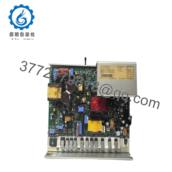
| Component Type | Signal Interface / Distribution PCBA |
| System Compatibility | VisionMaster FT Radar, ECDIS, and Conning Displays |
| Input Voltage | +5 V DC / +12 V DC (Bus Powered) |
| Data Protocols | NMEA 0183, RS-422, RS-232 |
| Isolation | Opto-coupling on critical I/O paths |
| Connectors | High-density ribbon cable headers & Terminal blocks |
| Operating Temp | -15 to +55 °C |
| Compliance | IEC 60945 (Exposed/Protected Navigation Equipment) |
4. Product Introduction
The Sperry Marine 65825816 is a mission-critical interface board designed for the VisionMaster FT navigation suite. In complex bridge architectures, this PCBA serves as the primary “translator,” aggregating data from the gyrocompass, GPS, AIS, and speed log to be overlaid onto the radar or ECDIS screen.
Precision-engineered to withstand the constant vibration and electromagnetic interference (EMI) found in a ship’s bridge console, the 65825816 features robust signal conditioning to prevent data corruption. Replacing an aging or lightning-damaged interface board with this genuine Sperry 65825816 ensures that your ARPA tracking and AIS overlays remain accurate—essential for maintaining SOLAS compliance and safe navigation in congested waters.
5. Installation & Configuration Guide
Stage 1: Pre-Installation Preparation (Estimated Time: 10 mins)
- ⚠️ Safety First: Completely isolate the workstation from the UPS power supply. Ensure the “Radar Standby” or “Scanner Off” command is active to prevent high-frequency interference during handling.
- Tools Required: PH1 screwdriver, ESD wrist strap (mandatory), and a digital multimeter for voltage verification.
- Documentation: Take a clear photograph of all connected ribbon cables and jumper settings on the old 65825816 board.
Stage 2: Removing the Old PCBA
- Open the processor chassis (usually located in the lower pedestal or electronics rack).
- Carefully unplug the multi-pin ribbon cables. ⚠️ Note: These connectors often have small locking clips; do not pull until they are released.
- Remove the mounting screws securing the board to the standoffs.
- Lift the board out by the edges. Inspect the backplane for any dust buildup that could cause a short.
Stage 3: Installing the New 65825816 (Estimated Time: 20 mins)
- ESD Prep: Work on an anti-static mat. This board contains high-speed logic chips that can be fried by a single static spark.
- Configuration Clone: Check for any DIP switches or solder-jumpers. These typically set the baud rates for NMEA inputs or define the board’s “ID” on the system bus. Match them exactly to the old board.
- Align the board with the standoffs and secure it. Do not over-tighten, as multi-layer PCBs can hairline-crack under stress.
- Reconnect the ribbon cables. Ensure the red stripe on the cable aligns with “Pin 1” on the header.
- Self-Checklist: [ ] Jumpers matched, [ ] Cables seated, [ ] Screws tightened.
Stage 4: Power-On & Testing
- Apply power to the workstation.
- Status LEDs: Most Sperry interface boards have “Status” or “Link” LEDs. Verify they are blinking in a healthy pattern (usually green).
- Enter the “Service Mode” on the VisionMaster display and verify that data from external sensors (Gyro, Log, GPS) is being received without “CRC Errors.”
- ⚠️ Troubleshooting: If a specific sensor is “Missing,” check the baud rate settings on the 65825816 jumpers or in the software port configuration.

- 65825816
6. Frequently Asked Questions (FAQ)
Q: Can this board be used for both Radar and ECDIS workstations?
A: Yes. In the VisionMaster FT architecture, the 65825816 is a versatile interface card used across the product line. Its specific function is determined by the software configuration and the physical ports it is connected to.
Q: Is this board “Hot-Swappable”?
A: No. Pulling this board while the system is live will likely cause a “System Exception” or “Blue Screen” on the Windows-based VisionMaster OS, and could potentially damage the motherboard’s PCI/bus interface.
Q: Why is my AIS data failing even after replacing this board?
A: If the board is new, the issue may be the AIS pilot plug wiring or a baud rate mismatch. Ensure the 65825816 is configured for 38,400 baud (High-Speed NMEA) for AIS, rather than the standard 4,800 baud.
Q: Is this “New Original” or a repaired/used part?
A: This is New Original (New Surplus). For maritime electronics, we only supply unused stock because repaired boards often fail prematurely under the thermal stress of a 24/7 operating bridge.
Q: Will this board fix an “Antenna Communication Error”?
A: Unlikely. “Antenna Communication Error” usually points to the transceiver aloft or the pedestal interface. The 65825816 handles sensor data; the radar video and scanner control are typically handled by a separate “Radar Interface” or “PCIO” board. Check your block diagram before ordering.
Q: Does it come with the required firmware?
A: The 65825816 is an interface board; the “intelligence” is driven by the main CPU and the VisionMaster software suite. No separate firmware flashing is typically required for the board itself, though the system may require a “Port Re-scan” in the service menu.


