
 WhatsApp: +86 16626708626
 Email:
  Phone: +86 16626708626
Description
3. Key Technical Specifications
| Parameter | Value |
|---|---|
| Component Type | PCIO (Processor Input/Output) Interface Board |
| System Compatibility | VisionMaster FT Radar, ECDIS, and Chart Radar |
| Input Channels | 8x NMEA 0183 (IEC 61162-1/2), RS-422 |
| Analog Inputs | 1x Speed Log (200 ppnm), 1x Gyro (Synchro/Step) |
| Radar Interface | Video, Trigger, and Azimuth/Heading Marker Inputs |
| Bus Interface | Standard System PCI/PCIe (Variant Dependent) |
| Operating Temp | -15 to +55 °C |
| Certification | IEC 60945 (Marine Type Approved) |
4. Product Introduction
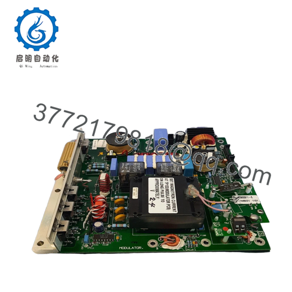
The Sperry Marine 65830812-03 is the primary hardware interface for the VisionMaster FT navigation suite. As a core PCIO (Processor Input/Output) board, it serves as the central hub for all sensor data, translating NMEA signals from the GPS, AIS, and Gyrocompass into a format the workstation software can process. Revision 03 features improved electromagnetic interference (EMI) shielding and updated logic controllers for higher data throughput.
In high-density traffic situations, the 65830812-03 is responsible for maintaining the synchronization between the radar transceiver and the ARPA tracking engine. Replacing a failing I/O board with this genuine Sperry 65830812-03 eliminates intermittent sensor dropouts and “Video Gate” errors, ensuring your bridge system meets all SOLAS requirements for navigation safety and accuracy.

- 65830812-03
- 65830812-03
5. Installation & Configuration Guide
Stage 1: Pre-Installation Preparation (Estimated Time: 15 mins)
- ⚠️ Safety First: Shut down the VisionMaster OS properly. Isolate the workstation from the AC/UPS power source.
- Tools Required: PH2 Phillips screwdriver, ESD wrist strap (mandatory), and a digital multimeter.
- Data Backup: Before shutting down, go to the Service Menu and take photos of the Port Configuration and I/O Mapping pages. You will need these to re-assign sensors to the new hardware.
Stage 2: Removing the Old PCBA
- Open the processor cabinet (usually a rackmount or pedestal-base PC).
- Carefully disconnect the high-density SCSI-style cables and internal ribbon headers. ⚠️ Warning: Use the plastic ejector tabs; do not pull on the cables themselves.
- Unscrew the retaining bracket from the chassis.
- Pull the board straight up to avoid damaging the bus pins. Inspect the motherboard for dust or heat marks.
Stage 3: Installing the New 65830812-03 (Estimated Time: 20 mins)
- ESD Prep: Ground yourself to the chassis. This board contains high-speed logic chips that are extremely sensitive to static.
- Configuration Check: Verify any DIP switches or jumpers on the -03 board match the old unit. These often define the board ID if multiple workstations are networked.
- Firmly seat the board into the slot. Secure the bracket and reconnect all external sensor cables.
- Self-Checklist: [ ] Board seated flush, [ ] Cables locked, [ ] Grounding screw tight.
Stage 4: Power-On & Commissioning
- Power up the workstation and enter the VisionMaster Service Mode.
- Hardware Detection: Confirm the OS recognizes the new PCIO board.
- Port Mapping: Re-assign the NMEA ports (e.g., Port 1 = Gyro, Port 2 = GPS).
- Signal Test: Verify “Live” data is appearing in the software for each active channel.
- ⚠️ Troubleshooting: If the radar video is missing, check the “Video Interlock” status in the service menu and verify the coax sub-header connection.
6. Frequently Asked Questions (FAQ)
Q: Can I replace a -01 or -02 revision with this -03 board? A: Yes. The 65830812-03 is backward compatible and replaces earlier revisions. It offers better component longevity and more stable data processing than the original -01 series.
Q: Why is my AIS data failing after swapping the board? A: This is usually a port mapping issue in the software. When the hardware is replaced, the Windows-based OS may assign it a different COM address. You must manually re-link the AIS sensor to the correct physical port in the Service Menu.
Q: Is this board “New Original” or a repaired/used part? A: This is New Original (New Surplus). In my experience, repaired I/O boards in marine environments are unreliable due to micro-corrosion on the traces. We only provide unused stock for mission-critical bridge equipment.
Q: Does this board handle the “Sync” for the radar scanner? A: Yes. The 65830812-03 manages the heading marker and azimuth pulses. If your radar image is “spinning” or losing North-up orientation, this board is a primary suspect.
Q: Will I need to re-install the VisionMaster software? A: No. The software should recognize the board automatically. You only need to calibrate the port settings and verify the sensor inputs.
Q: Will this board fix the “Radar Video Interlock” alarm? A: It often does. If the cable from the transceiver is good, the Interlock alarm usually points to a failure in the video processing circuit on the PCIO board. Replacing the 65830812-03 typically resolves this issue.


