
 WhatsApp: +86 16626708626
 Email:
  Phone: +86 16626708626
Description
3. Key Technical Specifications
| Parameter | Value |
|---|---|
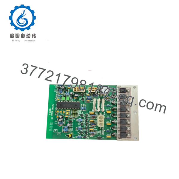
| Product Type | Motor Drive PCB |
| Application | X-band marine radar antenna control |
| Function | Controls antenna rotation motor |
| System Integration | Sperry Marine radar platforms |
| Output Type | Motor drive control signals |
| Power Input | System-integrated DC supply |
| Signal Processing | Embedded control circuitry |
| Mounting | Internal radar unit installation |
| Cooling | Passive (board-level heat dissipation) |
| Environment | Marine-grade, vibration-resistant |
| Lifecycle Status | Discontinued / secondary market sourcing |
| Variant Example | T65801811-9 (revision variant) |
4. Product Introduction & Supply Chain Strategy
The Sperry Marine T65801811 is a motor drive PCB used in X-band radar systems to control antenna rotation and scanning stability. It ensures consistent azimuth movement, directly impacting radar sweep accuracy and target detection reliability.
From an inventory strategy standpoint, this is a mission-critical failure point—if the board fails, the radar antenna stops rotating, effectively disabling the radar. With confirmed secondary-market-only availability, lead time variability is high. New Surplus procurement eliminates the risk of latent component fatigue found in refurbished PCBs. A minimum buffer stock of 1–2 units per vessel or radar system is justified to protect operational continuity and reduce Total Cost of Ownership (TCO).
5. Installation & Configuration Guide
Stage 1: Pre-Installation (Prep & Safety)
- Apply lock-out/tag-out on radar power supply.
- Discharge capacitors before handling internal electronics.
- Use ESD protection (grounded wrist strap).
- Photograph PCB connections and cable routing.
- Verify system voltage stability and grounding integrity.
Stage 2: Removal
- Open radar housing per OEM procedure.
- Disconnect connectors carefully—avoid pulling on wires.
- Remove PCB mounting screws evenly.
- Extract board without flexing to prevent microfractures.
Stage 3: Installation (Clone & Seat)
- Install replacement PCB in identical orientation.
- Reconnect all harnesses exactly as documented.
- Ensure secure seating and proper insulation clearance.
Stage 4: Power-On & Testing
- Reapply power and monitor radar startup sequence.
- Confirm antenna rotation is smooth and stable.
- Verify scan consistency and absence of motor jitter.
- Run radar self-test and observe fault indicators.

- T65801811
6. Firmware/Software Versions & Upgrade Notes
- Firmware Type: Embedded board-level control (not field-upgradable in most cases).
- Compatibility Note:
- Must match radar system generation (X-band platform variant).
- Revision differences (e.g., -9 suffix) may require validation.
- Critical Warning:
- Installing mismatched PCB revisions can cause rotation instability or failure to start.
- Avoid mixing board revisions without confirming compatibility.
- Best Practice: Replace like-for-like using identical part number and revision.
7. Frequently Asked Questions (FAQ)
Q1: Is this PCB truly new or just “open box”?
This product is a Brand New Surplus unit. It is not used, not removed from active radar systems, and not refurbished. It has zero solder repairs and no operational wear.
Q2: Why is this part critical for radar operation?
This PCB directly controls antenna rotation. If it fails, the radar cannot scan, resulting in total loss of situational awareness.
Q3: Is T65801811 still available from OEM?
No. This is a legacy component. Availability is limited to surplus channels, and supply is tightening.
Q4: What stocking strategy do you recommend?
- Minimum: 1 unit per radar system
- High-availability fleets: 2 units with cross-site sharing
- Consider vendor consolidation to secure remaining global inventory
Q5: What are the risks of refurbished PCBs?
Refurbished boards may have degraded capacitors or prior thermal stress. These hidden issues often lead to premature failure under continuous radar operation.
Q6: Can this board be repaired instead of replaced?
Component-level repair is risky and not recommended for mission-critical radar systems. Replacement with verified New Surplus ensures predictable reliability.
Q7: What warranty is provided?
12months warranty with full QC validation, including electrical testing, functional verification, and inspection sign-off prior to shipment.


