
 WhatsApp: +86 16626708626
 Email:
  Phone: +86 16626708626
Description
3. Key Technical Specifications
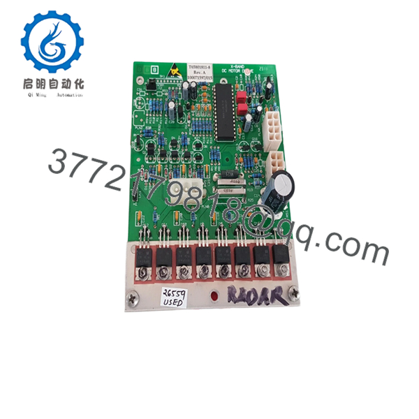
- Application: X-band marine radar scanner unit
- Function: DC motor drive control for antenna rotation
- Compatible Systems: Sperry Bridgemaster, VisionMaster FT
- Board Revision: Commonly Rev.A (field observed)
- Part Number: T65801811-8
- Associated Assembly Ref: 100071597/015
- Weight: ~200 g
- Signal Flow: Receives control signal → drives turning unit motor
- Installation Location: Radar scanner (antenna drive section)
- Operating Environment: Marine (salt mist, vibration, temperature cycling)
- Typical Condition on Market: Used / Refurbished / Open-box
4. Product Introduction
The Sperry Marine T65801811-8 is a motor drive PCB used in X-band radar scanner assemblies, specifically within Bridgemaster and VisionMaster FT navigation systems. It controls the DC motor responsible for rotating the radar antenna, a critical function for consistent azimuth scanning and target detection.
In field deployments, this board sits between the power supply and turning unit, translating control signals into stable motor drive output. It’s typically replaced due to wear in high-duty marine environments rather than outright failure—making verified functional testing more important than cosmetic condition.
5. Installation & Configuration Guide
Stage 1: Pre-Installation Preparation (Estimated: 10 minutes)
- ⚠️ Safety First:
- Notify bridge crew and disable radar transmission
- Lock out scanner power supply
- Wait 5 minutes for capacitor discharge
- Tools Required:
- ESD wrist strap
- PH1 screwdriver
- Multimeter (Fluke 115 recommended)
- Label tags + smartphone
- Data Backup:
- Record radar system status (fault codes if any)
- Photograph all connectors and board orientation
- Document cable routing (especially motor drive leads)
Stage 2: Removing the Old Module (Estimated: 5–10 minutes)
- Open radar scanner housing (weather-sealed cover)
- Identify motor drive PCB (typically mounted near drive motor assembly)
- Label and disconnect connectors (power + control harness)
- Remove mounting screws carefully (avoid dropping into scanner housing)
- Extract board without stressing connectors
- ⚠️ Note:
Keep the old board on-site until commissioning is complete. It’s your fallback.
Stage 3: Installing the New Module (Estimated: 10 minutes)
- ESD protection ON before handling PCB
- Verify part number T65801811-8 (suffix matters)
- Install board in identical orientation
- Reconnect wiring exactly as documented
- Tighten mounting screws (do not overtighten—PCB flex risk)
- Self-Checklist:
- Connectors fully seated
- No pin misalignment
- No loose wiring inside enclosure
- Gasket integrity maintained
Stage 4: Power-On & Testing (Estimated: 10 minutes)
- Pre-Power Check:
- Measure supply voltage to board (typically stable DC rail from PSU)
- Check for short circuits
- Power-On Steps:
- Energize radar system
- Observe antenna rotation startup
- Verify smooth rotation (no jitter or stalls)
- Confirm radar sweep on display
- Monitor for abnormal noise or overheating
- ⚠️ Troubleshooting Notes:
- No rotation → check motor output stage or upstream PSU
- Intermittent rotation → often connector oxidation or relay fatigue
- Erratic speed → control signal instability

- T65801811-8
- T65801811-8
6. Frequently Asked Questions (FAQ)
Q1: Can this PCB be hot-swapped?
No. This is inside the radar scanner assembly. Power must be fully isolated.
Hot-swapping risks damaging both the PCB and upstream power supply.
Q2: Is this model obsolete?
Yes. This board is tied to legacy Sperry radar systems.
Stock is limited and mostly comes from surplus or refurbished sources.
Q3: What systems is it compatible with?
Primarily Bridgemaster and VisionMaster FT radar systems.
Always verify against your scanner unit part list—Sperry has multiple minor revisions.
Q4: Why do these boards usually fail?
In my experience, it’s rarely catastrophic failure. Common causes:
- Salt ingress over years
- Thermal cycling cracking solder joints
- Motor load stressing output stage
Q5: Will replacing this board fix a non-rotating antenna?
Not always. About 50% of cases I’ve seen were actually:
- Seized antenna bearings
- Faulty power supply module
- Wiring harness issues
Always test the motor independently before swapping the PCB.
Q6: Why are prices inconsistent across suppliers?
Because supply is not factory-driven anymore.
You’re buying from:
- Ship recyclers
- Marine spare dealers
- Independent refurbishers
Condition and testing quality vary significantly.
Q7: Is refurbished acceptable for this application?
Yes—if properly tested.
For marine radar, I’d prioritize:
- Functional load testing
- Clean connectors
- No corrosion on traces
A cosmetically “new-looking” board is less important than electrical stability.
SOP Quality Transparency (How Units Are Verified)
1. Inbound Inspection & Traceability
- Verified against supplier documentation and part markings
- Visual inspection under magnification (no corrosion or rework marks)
- Connector integrity checked (no pin oxidation)
2. Live Functional Testing
- Tested on a simulated radar drive setup (motor + PSU loop)
- Power-on verification (stable output drive)
- Continuous operation test (24-hour rotation simulation)
- Thermal monitoring during load
3. Electrical Testing
- Insulation resistance test (>10 MΩ @ 500 V Megger)
- Ground continuity check
- Output stage voltage stability measurement
4. Firmware / Configuration
- No firmware dependency (hardware-level board)
- Connector mapping verified against known reference
5. Final QC & Packaging
- Anti-static ESD packaging
- Shock-protected boxing
- QC label with test date
Test photos and videos available on request.
Technical Pitfall & Survival Guide
❗ 1. Misdiagnosing the Failure
I’ve seen engineers swap this board only to find the antenna still dead.
Turns out the motor bearings were seized.
Check motor free rotation manually before replacement.
❗ 2. Connector Orientation Mistakes
These boards often use similar connectors.
Take photos before removal.
Plugging motor output into control input can damage the board instantly.
❗ 3. Ignoring Power Supply Health
A failing PSU will kill your replacement board.
Measure voltage stability under load before installing a new PCB.
❗ 4. Environmental Contamination
Salt and humidity are silent killers.
I’ve opened scanner units where condensation had already started corroding traces.
If you don’t fix sealing, you’ll be replacing this board again in 6 months.
❗ 5. ESD Damage During Handling
This is not forgiving hardware.
I’ve personally watched a technician destroy a replacement board on installation day.


