

 WhatsApp: +86 16626708626
 Email:
  Phone: +86 16626708626
Description
3. Key Technical Specifications
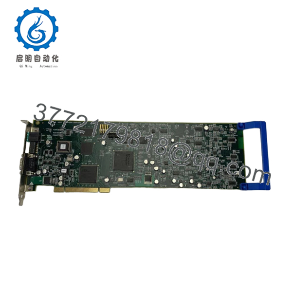
- Interface Type: Standard PCI bus
- External Connector: DAVINCI interface port
- Function: Radar scan signal conversion and processing
- Application: Marine radar and navigation systems
- PCB Type: Industrial multi-layer board with integrated ICs
- Mounting: Slot-in PCI card (rack/industrial computer)
- Cooling: Passive (convection via enclosure airflow)
- Operating Environment: Marine bridge systems (typically 0 to +55°C, verify OEM spec)
- Handling Feature: Integrated side handle for insertion/removal
- Part References: Article No. 40004790 / FZ000399
4. Product Introduction
The Sperry Marine T65900810-3 is a PCI-based scan converter PCB used in marine radar and navigation systems. It processes and converts radar scan signals for display and integration within bridge systems.
In field deployments of Sperry Marine radar platforms, this type of board typically sits between the radar processing unit and visualization layer. The PCI interface and DAVINCI connector indicate integration with proprietary marine computing platforms. It’s selected when maintaining legacy radar systems where exact hardware matching is required to avoid software and signal incompatibility.
5. Installation & Configuration Guide
Stage 1: Pre-Installation Preparation (Estimated: 10–15 minutes)
- ⚠️ Safety First:
Notify bridge/operations. Power down radar system. Lock out power. Wait at least 5 minutes for capacitor discharge. - Tools Required:
ESD wrist strap, PH1 screwdriver, multimeter, labeling tape, smartphone - Data Backup:
- Capture system configuration (radar processor settings)
- Photograph slot position and cable routing
- Document any external connector (DAVINCI) wiring
Stage 2: Removing the Old Module (Estimated: 5–10 minutes)
- Open radar processing unit enclosure
- Label all external connectors (especially DAVINCI interface)
- Carefully disconnect cables (no twisting force)
- Release PCI retention bracket
- Pull the board straight out — do not tilt (protect backplane connector)
- Inspect PCI slot for corrosion or debris
- ⚠️ Note: Keep the original board on-site for reference until commissioning is complete
Stage 3: Installing the New Module (Estimated: 5–10 minutes)
- Wear ESD protection before handling
- Verify model: T65900810-3 must match exactly
- Insert board into PCI slot — firm, even pressure
- Secure bracket to chassis
- Reconnect DAVINCI and any auxiliary cables
- Self-Checklist:
- Board fully seated
- Connectors aligned and locked
- No pin damage
Stage 4: Power-On & Testing (Estimated: 10–15 minutes)
- Pre-Power Check:
Measure 24 V supply rail for shorts - Power-On Steps:
- Energize processing unit (leave radar transmitter off initially)
- Verify system boots without PCI fault
- Check radar display initialization
- Validate scan conversion output (image rendering)
- Enable radar transmitter and perform live test
- ⚠️ Troubleshooting Note:
- No display output → likely interface mismatch or board not detected
- Intermittent signal → check DAVINCI connector seating
6. Frequently Asked Questions (FAQ)
Q1: Can this board be hot-swapped?
No. This is a PCI-based board inside a marine processing unit. Hot-swapping will likely damage the backplane or corrupt the system. Power down fully before removal.
Q2: Is this model obsolete?
In practical terms, yes. This is tied to legacy Sperry Marine radar platforms. Availability is limited and typically comes from surplus inventory.
Q3: Is there a direct replacement?
Not in the generic sense. Replacement must match the exact part number. Newer Sperry Marine systems use different architectures and are not backward-compatible at board level.
Q4: Will I lose system configuration when replacing it?
No, configuration is typically stored in the host system, not on this PCB. However, if the system firmware expects a specific hardware revision, mismatches can prevent startup.
Q5: Why is availability inconsistent?
These boards are no longer in active production. Most stock comes from decommissioned vessels or surplus channels. I’ve seen lead times jump from 2 days to 8 weeks depending on global availability.
Q6: What’s the most common installation mistake?
❗ Not checking connector alignment.
The DAVINCI connector is not forgiving — misalignment causes intermittent faults that look like software issues.
SOP Quality Transparency (Inspection & Testing Process)
1. Inbound Inspection & Traceability
- Verified against OEM labeling (P/N: T65900810-3, internal refs)
- Visual inspection under magnification: no solder rework, oxidation, or connector wear
- Connector pins checked for deformation
- Packaging and labeling cross-checked with supplier documentation
2. Live Functional Testing
- Tested on a marine radar processing rack (PCI backplane system)
- Power-on verification: stable initialization
- PCI bus recognition confirmed via system diagnostics
- Signal path simulation: radar scan data emulation
- Continuous runtime test: >24 hours under load
- Test reports and video evidence available upon request
3. Electrical Parameter Testing
- Insulation resistance: >10 MΩ @ 500 V (Megger)
- Ground continuity verified
- Voltage rail stability checked using Fluke 115 multimeter
4. Firmware & Configuration Verification
- Hardware revision documented
- No onboard firmware conflicts detected (pass-through processing board)
- Connector mapping verified
5. Final QC & Packaging
- QC sign-off with traceable ID
- ESD-safe packaging
- Reinforced industrial carton
- Shock protection for international shipping

- T65900810-3
- T65900810-3
Technical Pitfalls & Survival Guide
1. Firmware/System Compatibility
❗ Even though this is a hardware board, the host radar system firmware expects specific hardware IDs.
I’ve seen systems fail to boot because a slightly different revision was installed.
Avoidance: Confirm compatibility with your radar processor model before ordering.
2. Connector Misalignment (DAVINCI Port)
❗ This is the #1 field issue.
Looks connected, but it’s not fully seated → intermittent radar loss.
Avoidance: Physically inspect alignment and lock mechanism. Don’t rely on feel alone.
3. PCI Slot Wear in Marine Environments
Salt air + vibration = oxidized contacts.
Avoidance: Clean slot with contact cleaner before inserting the new board.
4. Power Supply Stability
Older radar systems often have marginal PSUs.
Avoidance: Measure voltage under load. Keep at least 15–20% margin.
5. ESD Damage During Handling
❗ Marine environments are dry enough to build static.
I’ve personally seen a board fail instantly after improper handling.
Avoidance: Always use grounded wrist strap and ESD mat.


