
 WhatsApp: +86 16626708626
 Email:
  Phone: +86 16626708626
Description
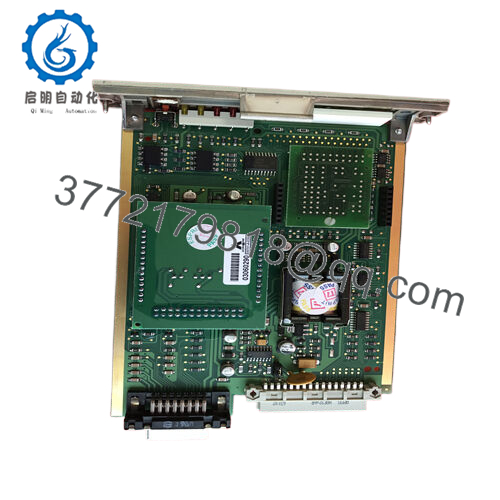
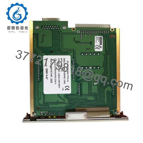
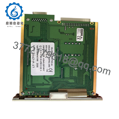
Product Model: 05701-A-0301
Product Brand: Honeywell (Zellweger / Honeywell Analytics)
Product Series: System 57 / 5701 Control Cards
Key Features (from vendor sources):
- Single channel control card for use in System 57 / 5701 gas detection / analytic systems, handles 4–20 mA input type.
- Provides control, display, alarm logic, and data processing for an individual detection channel.
- Operates from 18–32 V DC supply.
- Typical power consumption: ~ 3.25 W (for 4–20 mA mode) including associated sensor drive load.
Product Role & System Fit
The 05701-A-0301 card is part of Honeywell’s System 57 / 5701 architecture, used for industrial gas detection, process monitoring, and safety systems. In that environment, each process or detection channel (gas sensor, catalytic sensor, etc.) must be interfaced, processed, alarmed, and validated. 05701-A-0301 is a single channel control card managing exactly one detection loop.
Its job is multifaceted: it accepts a conditioned sensor input (often 4–20 mA), applies logic (alarm thresholds, fault handling), drives the front panel indicators / displays, communicates with the rack bus / system backbone, and triggers relay outputs or higher-level warnings. Vendor text states it “provides control, display and alarm for a gas detector, processing signals, displaying levels, and raising alarms.”
Because there is a range of similar control cards (e.g. the catalytic version 05701-A-0302), the 0301 variant is tuned specifically for 4–20 mA sensor inputs.
In a System 57 rack, multiple 05701-A-0301 cards may be inserted alongside other channel cards. The system’s Engineering Card (e.g. 05701-A-0361) will allow setting parameters, selecting which cards are active, reading diagnostics, etc. (Note: System (rack) must be programmed to accept card types)
That means when you install a 05701-A-0301 card, you’re inserting one loop’s “brain” — it must be configured, powered, wired to the sensor, and integrated with the rack’s logic.

- 05701-A-0301

Technical Features & Benefits
Here’s a closer look at what 05701-A-0301 provides, as seen in datasheets / vendor descriptions:
Input & Signal Handling
- The card accepts 4–20 mA sensor input — the standard industrial current loop.
- It includes sensor drive modules (plug-in) that condition and energize sensors; the 0301 card works with the 4–20 mA sensor drive module (part 05701-A-0283) that plugs directly into the control card.
- Optionally, an Analogue Output Module (part 05701-A-0285) may be fitted to 0301 to enable an isolated 0–20 mA or 4–20 mA analog output reflecting the measured value.
Display, Alarm & Logic
- The control card includes a front panel LCD display that shows gas level or measured value, and channel status.
- LED indicators (e.g. A1, A2, A3) display alarm states; a FAULT or INHIBIT LED may also be present.
- A push-button interface enables Alarm Reset / Card Select, to allow user interaction from the front panel.
- Alarm thresholds (e.g. high alarm, high-high alarm) are user-configurable in percentage steps (e.g. 1 % resolution).
- On exceeding thresholds, the card triggers relay outputs or communicates alarm state to system logic.
Power, Consumption & Physical
- The card operates from 18–32 VDC supply.
- A listing states power consumption in 4–20 mA mode is ~ 3.25 W.
- When used with catalytic sensor mode, consumption including sensor is ~ 3.75 W.
- The card’s physical dimensions are about 17.0 cm × 2.5 cm × 11.2 cm (L × W × H).
- Weight is ~ 0.165 kg (165 g) for the card itself.
Calibration, Memory & Drift
- The card uses EEPROM to store configuration, calibration, and user settings.
- It self-validates internal circuits, software operations, and sensor condition.
- Electronic drift is cited as less than ±2 % over 6 months.
Technical Specifications Table
Below is a consolidated spec table based on vendor sources and inferences:
| Specification | Value / Range | |
|---|---|---|
| Model | 05701-A-0301 | |
| Type | Single Channel Control Card (4–20 mA) | |
| Input Type | 4–20 mA sensor input | |
| Sensor Drive Module | Module 05701-A-0283 plugs in | |
| Optional Analogue Output | 0–20 or 4–20 mA via module 05701-A-0285 | |
| Supply Voltage | 18–32 VDC | |
| Power Consumption | ~3.25 W (4–20 mA mode) | |
| Dimensions (L × W × H) | ~17.0 × 2.5 × 11.2 cm | |
| Weight | ~0.165 kg | |
| Drift | < ±2 % over 6 months | |
| Functions | Display, Alarm logic, Self test, Configuration memory |
This table is a useful guide but should be cross-checked with your physical card or official Honeywell documentation before final design or replacement.
Installation & Maintenance Insights
Here are field-proven tips and cautions when deploying or servicing 05701-A-0301:
Rack Integration & Slot Insertion
- Always power down or isolate the System 57 rack before inserting or removing the control card to avoid backplane damage.
- Align card edges carefully — avoid bending or damaging connector pins.
- Ensure the card is fully seated and secured to maintain reliable contact.
Power & Wiring
- Verify that the DC supply is within the 18–32 V range, with sufficient current headroom.
- Use proper wiring gauge, shielding, and separation from power lines to avoid noise injection into sensor circuits.
- Tighten terminal connections per recommended torque to maintain signal integrity.
Sensor & Signal Connection
- Ensure the 4–20 mA sensor leads are properly connected, respecting polarity and shielding.
- If driving optional analogue output modules, check isolation pathways and grounding to avoid loops.
- For catalytic or other sensor types, ensure the correct sensor drive module is plugged in (e.g. 0283 or its counterpart).
Configuration & Calibration
- Use the Engineering / setup interface (Engineering Card) to configure card type, alarm setpoints, ranges, and enable/disable diagnostics.
- After installation, validate sensor zero/span, check alarms, and run diagnostics.
- Regular calibration (e.g. periodic span checks) is important to maintain accuracy and reduce drift over time.
Diagnostics & Fault Handling
- Use front-panel LEDs to check status (Alarm, Fault, Inhibit).
- If the card reports self-test or error faults, use engineering interface to read error codes (EEPROM mismatch, sensor fault, drift).
- Monitor drift over time. If per-channel drift exceeds specification (>2% in 6 months), plan recalibration or replacement.
Spare / Replacement Strategy
- Because this is a critical channel logic card, maintain at least one spare 05701-A-0301 or compatible variant.
- Ensure the spare has the same firmware/revision to avoid compatibility issues.
- Always backup configuration parameters (alarm thresholds, type, channel ID) to speed swap and reduce downtime.
Environmental & Wear Considerations
- Avoid exposure to excessive heat, humidity, vibration, or corrosive gases, which can degrade display, circuits, or connectors.
- Periodically inspect for signs of corrosion, connector oxidation, or mechanical damage (especially around connectors or terminal screws).
Because control cards like 0301 govern alarms and safety loops, their reliability is directly tied to system integrity. Preventive maintenance, spares, and careful configuration are key.
Related Models & Compatibility Notes
- 05701-A-0302 – The catalytic sensor variant of the control card (for catalytic gas sensing) rather than 4–20 mA type.
- 05701-A-0283 – Sensor drive module (4–20 mA type) that plugs into the control card.
- 05701-A-0285 – Optional analogue output module to add 0–20 or 4–20 mA remote output for the control card.
- 05701-A-0351 – Another control or configuration card in the 5701 family.
- 05701-A-0361 – The Engineering / Maintenance / Setup card for System 57, used to configure cards like 0301.
One note: System 57’s rack must be programmed (via EIS57 or other tools) to accept mixed card types (e.g. 0301 and 0302) if different variants are installed in the same rack.


