
 WhatsApp: +86 16626708626
 Email:
  Phone: +86 16626708626
Description
2. Product Core Brief
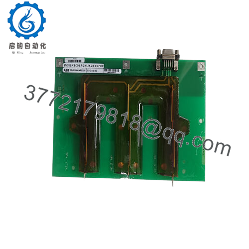
- Model: KSD211B (3BHE022455R1101 / KS D211 B101)
- Brand: ABB
- Series: UNITROL Excitation Systems (Power Electronics)
- Core Function: Signal input coupling and isolation
- Product Type: Input Coupling Unit (ICU)
- Key Specs: Galvanic isolation, multiple input channels, excitation controller interface
- Condition: New Original / New Surplus
- ⚠️ Obsolete Model – Limited Stock Available
3. Key Technical Specifications
- Function: Input signal coupling/isolation for UNITROL excitation
- Channels: Multiple analog/digital inputs (exact count per config; typically for reference, feedback, sensors)
- Isolation: Galvanic between field inputs and controller electronics
- Input Types: Voltage/current signals, sensor interfaces (e.g., PT/CT feedback, setpoints)
- Power Supply: Derived from excitation system (typically 24 V DC or system bus)
- Operating Temperature: –20°C to +60°C (typical for UNITROL modules; verify datasheet)
- Dimensions: Approx. 120 mm depth/length × 165 mm height × 50 mm width (from similar listings)
- Weight: Approx. 0.5 kg (net; 0.45–0.5 kg shipping variants)
- Mounting: Plugs into UNITROL rack or excitation cabinet
- Country of Origin: Switzerland (CH) common
- Customs Tariff: 85437000 (electronics category)
4. Product Introduction
The ABB KSD211B (3BHE022455R1101) is an Input Coupling Unit (ICU) within ABB UNITROL static excitation systems for synchronous generators. It couples external input signals—such as voltage references, current feedback, or protection inputs—into the excitation controller while providing essential isolation against ground loops and noise.
In turbine-generator excitation systems I’ve commissioned, this ICU maintains clean signal integrity under high-EMI plant conditions, preventing false triggers or drift in AVR response. It’s a critical spare for legacy UNITROL installations in power plants, where downtime from signal faults can cascade to grid instability.

- KSD211B 3BHE022455R1101
5. Installation & Configuration Guide
Replacing the KSD211B in a UNITROL excitation cabinet requires full excitation shutdown—plan 45–120 minutes downtime, including lockout and testing. Not hot-swappable.
Stage 1: Pre-Installation Preparation (15–30 min) ⚠️ Safety First: Lock out/tag out excitation power, field breaker, and auxiliaries. Discharge capacitors (wait 10+ min; verify 0 V on terminals). Ground if required. Coordinate with operations for generator offline. Tools Required: ESD wrist strap, PH1/PH2 screwdriver, multimeter, torque tool, camera/phone, wire labels. Data Backup: Upload excitation parameters via UNITROL interface/tool. Photograph module position, terminal wiring, any jumpers/settings, and cable routing.
Stage 2: Removing the Old Module (10–20 min)
- Open cabinet; confirm de-energized.
- Label and disconnect input/output terminals (note polarity/shielding).
- Release locking tabs/clips on rack mount.
- Pull module straight out to protect pins.
- Inspect backplane/connector for damage, dust, or oxidation.
⚠️ Note: Retain old unit labeled until new one fully tested—critical for diagnostics.
Stage 3: Installing the New Module (15–30 min)
- ESD strap on; verify exact match: 3BHE022455R1101 / KSD211B.
- Set jumpers/config (if any) from photos (rare but check for input type).
- Insert into slot; ensure firm backplane connection (click).
- Secure tabs.
- Reconnect wiring exactly as documented (torque per manual; maintain shielding).
Self-Checklist: [ ] Match part number, [ ] Jumpers correct, [ ] Wiring polarity/shield right, [ ] Seated fully.
Stage 4: Power-On & Testing (20–60 min) Pre-Power Check: Multimeter for shorts on inputs to ground; continuity checks. Power-On Steps:
- Restore aux/excitation power per UNITROL sequence.
- Observe status LEDs (if present; green healthy, red fault).
- Access UNITROL HMI/tool; verify module detected/online.
- Check input signal values (e.g., reference, feedback) match expected.
- Perform excitation test (no-load, then incremental field); monitor for alarms.
- Run stability checks; log events.
⚠️ Troubleshooting Note: No signal pass-through or ERR? Reseat, check wiring/continuity. Noisy inputs? Verify shielding/grounding. AVR instability post-swap? Recalibrate gains or confirm isolation integrity.
6. Frequently Asked Questions (FAQ)
Can this ICU be hot-swapped? No. UNITROL excitation involves high field voltages—live replacement risks shock, arc flash, or controller damage. Full lockout/tagout required.
Is the KSD211B 3BHE022455R1101 obsolete? Yes, part of legacy UNITROL platforms; no new production. Spares from surplus/stock—availability limited and declining for installed generators.
What is the direct replacement if unavailable? No exact drop-in; ABB may offer supersessions or kits for UNITROL upgrades. For migrations, transition to newer UNITROL 1020/6000 series with equivalent I/O coupling. Match signal types/isolation ratings precisely.
Will excitation parameters be lost during swap? No—parameters stored in controller/AVR, not the ICU. Upload/download via tool before/after. Still, verify post-install to avoid tuning drift.
Why is the price lower than ABB direct? Sourced new surplus/excess meeting specs but skipping factory channels. Units undergo visual/traceability checks, power-up test (LEDs/comm if applicable), basic insulation/continuity. Not ABB recertified unless stated.
What testing do you perform? Inbound: visual (no corrosion/damage), power-on in simulation rack (status indicators), input/output continuity if testable, insulation resistance. Detailed photos/reports available.
How do I confirm compatibility with my UNITROL system? Match exact part number against excitation BOM or existing label. Check revision against UNITROL manual. If inputs (e.g., PT/CT ratios) differ, verify config. Photo old module and cross-reference ABB UNITROL docs or service records when possible.


