
 WhatsApp: +86 16626708626
 Email:
  Phone: +86 16626708626
Description
Key Technical Specifications
- Protection Principle: Phase-segregated line differential (LNPLDF) with low/high sensitivity stages
- Communication: Fiber-optic link (preferred) or galvanic pilot wire between ends; IEC 61850-8-1, GOOSE support
- Current Inputs: 3-phase + 1 residual (5 A or 1 A nominal; sensor option available)
- Binary Inputs/Outputs: Configurable, typically 8-16 BI, 6-10 PO/SO depending on variant
- Power Supply: 24-265 V AC/DC (wide range PSU module)
- Operating Temperature: -25 to +55 °C (standard); extended -40 to +70 °C available
- Accuracy: Differential current < ±5% typical; time synchronization via IRIG-B or SNTP
- Mounting: Panel (flush/semi-flush) or DIN-rail; 1/2 19″ rack width
- Dimensions (approx.): 177 mm H × 177 mm W × 158 mm D (half 19″ case)
- Weight (approx.): 4.5-5.0 kg depending on options
- Firmware: Product version 5.0 FP1 or earlier legacy (document version before swap)
- Certifications: IEC 60255 series, EMC/LVD compliant

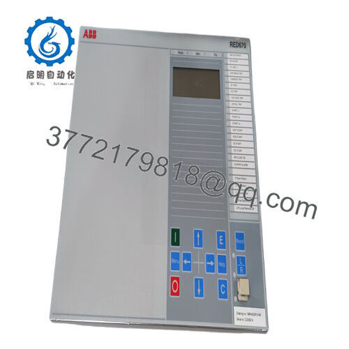
- RED615
The ABB RED615 is a member of the Relion 615 series, serving as a compact IED for phase-segregated two-end line differential protection and control of overhead lines and cable feeders in utility and industrial medium-voltage distribution networks.
It handles radial, looped, and meshed configurations, including those with distributed generation or in-zone transformers. The relay uses fiber-optic communication for reliable inter-substation differential signaling or pilot wire as fallback—chosen widely for its IEC 61850 integration and proven stability in brownfield upgrades where minimal disruption is critical.
Installation & Configuration Guide
Stage 1: Pre-Installation Preparation (20–30 minutes) ⚠️ Safety First: Schedule downtime with operations. Isolate line, open breakers, ground if required. Lock out/tag out auxiliary power to IED. Wait 5–10 minutes for discharge. Tools Required: Grounded ESD strap, PH1/PH2 screwdriver, torque driver (per terminal specs), multimeter, laptop with PCM600, camera for photos. Data Backup: Connect via PCM600 or IED front port. Export full configuration, parameters, disturbance records. Photograph LHMI settings, DIP switches (if any on comm module), terminal wiring, LED status.
Stage 2: Removing the Old Module (15 minutes)
- Open panel door, locate RED615 in rack or flush mount.
- Label and disconnect all CT/VT wires, binary I/O, comm fibers/pilot wires, aux power (do not mix polarities).
- Release mounting screws/clips. Pull unit forward carefully—avoid straining backplane or fiber connectors.
- Inspect case terminals and fiber ports for dust, corrosion, or damage—clean with approved tools. ⚠️ Note: Keep old IED intact as reference until replacement is commissioned and tested.
Stage 3: Installing the New Module (20–25 minutes)
- Ground with ESD strap. Verify order code matches original (e.g., same analog input rating, comm module type).
- Configuration Clone (Crucial): Use PCM600 to read old config if possible; otherwise, mirror all settings manually. Pay attention to line differential parameters (CT ratios, line length, charging current compensation), comm channel setup, address/node IDs.
- Insert into panel/rack—secure with torque specs (typically 1–2 Nm).
- Reconnect all wires/fibers exactly as labeled (check fiber Tx/Rx polarity; torque terminals 0.5–1 Nm). Self-Checklist: [ ] Order code identical, [ ] Settings/parameters matched, [ ] Wiring/fiber secure and correct, [ ] Mounting fixed.
Stage 4: Power-On & Testing (30–60 minutes) Pre-Power Check: Multimeter verify no shorts on aux supply, CT circuits open (no current). Power-On Steps:
- Apply aux power only (keep CTs shorted initially).
- Observe LHMI LEDs: Green power/RUN good; red/alarm indicates fault (check self-supervision).
- Connect PCM600; verify IED boots, firmware version, comm link status (differential healthy).
- Download config if needed; enable protection.
- Test: Inject test currents for differential operate, check blocking, autoreclose if configured; verify remote end sync. ⚠️ Troubleshooting Note: Comm fail or differential alarm? Check fiber continuity, Tx/Rx swap, channel delay asymmetry. ERR LED? Firmware mismatch or config error—reload from backup.
Frequently Asked Questions (FAQ)
Can the RED615 be hot-swapped? No. Power down aux supply before removal/insertion. Live swapping risks IED damage, false trips, or comm disruption in differential schemes.
Is RED615 obsolete, and is the stock new? Not fully obsolete—current versions at 5.0 FP1 IEC/ANSI—but many early configs are legacy with limited production. We supply new surplus/original from verified spares; fully tested (power-on, comms simulation, thermal >24 hours, insulation >10 MΩ). Traceability provided.
What is the direct replacement if RED615 unavailable? No pin-for-pin drop-in; migrate to RED670 (Relion 670 series) for advanced line diff or REF615 for feeder-only. Requires config conversion, wiring checks, comm re-engineering—assess via ABB tools.
Will swapping lose protection settings or logic? No, if backed up via PCM600 before removal. Battery retains non-volatile memory short-term. Always export full project file first; reload post-swap. I’ve seen partial losses from dead batteries—test backup immediately.
Why is the price lower than ABB direct? New surplus from project overstock, decommissioned substations, or excess—no OEM production overhead. Full QC applied (functional, electrical, load simulation) before ship.
How to handle communication setup or firmware? Use PCM600 for config/firmware management. Document old version—mismatch causes comm supervision alarm or block. Fiber link needs matched modules at both ends. Test reports/photos available.
Keep PCM600 backups current and photograph every detail before pulling—skipping that adds hours or days chasing mismatches. Cross-check your specific order code, comm type (fiber vs pilot), and application manual against ABB datasheets before energizing.


