
 WhatsApp: +86 16626708626
 Email:
  Phone: +86 16626708626
Description
3. Key Technical Specifications
| Parameter | Value |
|---|---|
| System Type | Rectifier shelf / power system |
| Output Voltage | 24 V DC nominal |
| Form Factor | 3U rack-mounted shelf |
| Manufacturer | Tectrol (integrated into Alcatel systems) |
| Function | AC to DC conversion + power distribution |
| Architecture | Modular rectifier slots (N+1 redundancy capable) |
| Input Voltage | Typically 90–264 VAC (depends on rectifier modules) |
| Cooling | Forced airflow via shelf design |
| Application | Telecom base stations, switching systems |
| Lifecycle Status | Discontinued / legacy telecom infrastructure |
| Cross Reference | KS24729 / related rectifier shelf assemblies |
4. Product Introduction
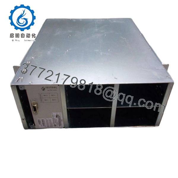
The Alcatel-Lucent TECTROL TCPR-3U-24-1432 is a 3U rectifier shelf used in telecom power systems to convert AC input into regulated 24 V DC for network equipment. It is part of a modular power architecture where multiple rectifier modules are inserted into the shelf.
In field deployments (especially older BTS and central office setups), this shelf acts as the primary DC power backbone. The design supports parallel rectifier operation with redundancy, which is critical for maintaining uptime in telecom environments where even short outages are unacceptable.
5. Installation & Configuration Guide
Stage 1: Pre-Installation Preparation (Estimated: 15–20 minutes)
- ⚠️ Safety First:
Notify NOC. Isolate load. Turn off AC input breakers. Lock out/tag out. Wait 5–10 minutes for discharge. - Tools Required:
ESD strap, insulated screwdriver, multimeter (Fluke 115 class), torque wrench, PPE gloves - Data Backup:
- Record DC output voltage and load current
- Document rectifier module positions
- Photograph wiring (AC input and DC bus bars)
Stage 2: Removing the Old Shelf (Estimated: 15–20 minutes)
- Disconnect AC input feeds
- Disconnect DC output cables (label polarity clearly)
- Remove rectifier modules (if hot-swappable, remove individually)
- Unscrew rack mounting points
- Slide shelf out carefully
- ⚠️ Critical: DC bus bars can still hold residual charge—verify with multimeter
Stage 3: Installing the New Shelf (Estimated: 20–25 minutes)
- Apply ESD and electrical safety precautions
- Mount 3U shelf securely in rack
- Reinstall rectifier modules into slots
- Connect AC input wiring
- Connect DC output (correct polarity is critical)
- Self-Checklist:
- AC wiring secure
- DC polarity correct
- Modules fully seated
Stage 4: Power-On & Testing (Estimated: 20–30 minutes)
- Pre-Power Check:
Measure insulation and verify no short between +24 V and ground - Power-On Steps:
- Energize AC input
- Verify rectifier modules initialize
- Measure DC output (should stabilize around 24 V)
- Apply load gradually
- Monitor alarms and current sharing
- ⚠️ Troubleshooting Note:
- Uneven load sharing → faulty rectifier module
- No output → check AC input and control wiring

- TCPR-3U-24-1432
6. Frequently Asked Questions (FAQ)
Q1: Can I hot-swap rectifier modules in this shelf?
Usually yes, but not the shelf itself.
Rectifier modules are typically hot-swappable, but replacing the entire shelf requires full shutdown.
Q2: Is TCPR-3U-24-1432 still supported?
No.
This belongs to older telecom power systems. Most units available today are surplus or refurbished.
Q3: What’s the difference between 24V and 48V telecom systems?
48 V is more common today.
24 V systems are older or used in specific deployments. Mixing them is not possible—equipment must match voltage.
Q4: What happens if polarity is reversed?
❗ Immediate risk of damage.
I’ve seen entire BTS racks taken offline due to reversed DC connections.
Q5: Why is load sharing important?
Multiple rectifiers must share current evenly.
If one carries more load, it overheats and fails early.
Q6: Most common field issue?
❗ Loose DC terminals.
High current + poor contact = heat buildup and eventual failure.
SOP Quality Transparency (Inspection & Testing Process)
1. Inbound Inspection & Traceability
- Verified P/N: TCPR-3U-24-1432 / KS24729 equivalent
- Visual inspection: no corrosion, no bus bar damage
- Connector and slot integrity checked
2. Live Functional Testing
- Installed with compatible rectifier modules
- AC input applied and DC output verified
- Load test performed with resistive load bank
- 24-hour continuous operation test
- Test logs and videos available upon request
3. Electrical Parameter Testing
- Insulation resistance: >10 MΩ @ 500 V
- Ground continuity verified
- Output voltage stability monitored
4. Firmware & Configuration Verification
- Shelf control interface verified (if applicable)
- Module communication checked (I²C/alarm signaling typical)
5. Final QC & Packaging
- Bus bars protected with insulation covers
- ESD-safe packaging
- Heavy-duty reinforced carton
- QC Passed label with traceable ID


