
 WhatsApp: +86 16626708626
 Email:
  Phone: +86 16626708626
Description
Product Core Brief
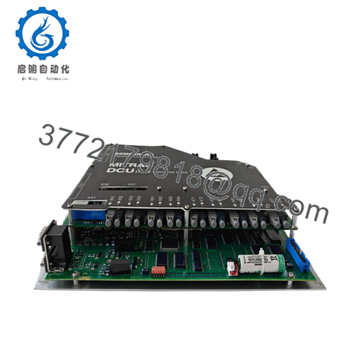
- Model: 3EST125-975 (DCC2382A series)
- Brand: Bombardier
- Series: Industrial Drive Control Systems
- Core Function: Motor drive power electronics control
- Product Type: DIN rail mounted control module
- Key Specs: 12.7 × 22.9 × 17.8 cm, 3.3 kg, 24 VDC logic
- Condition: New Original / New Surplus
Key Technical Specifications
| Parameter | Value |
|---|---|
| Dimensions | 12.7 × 22.9 × 17.8 cm |
| Weight | 3.3 kg |
| Mounting | DIN rail compatible |
| Power Supply | 24 VDC control logic |
| I/O Type | Digital/analog mixed |
| Operating Temperature | -20°C to +60°C |
| Communication | Modbus RTU RS485 |
| Enclosure Rating | IP20 |
| Country of Origin | USA |
| Application | Industrial motor drives |

- 3EST125-975 DCC2382A
Product Introduction
The Bombardier 3EST125-975 is a drive control module from the DCC2382A family used in industrial motor drive systems and automation equipment. It handles power stage switching, feedback processing, and communication for variable frequency drives in manufacturing and process control.
Engineers integrate it into DIN rail assemblies where compact size and Modbus connectivity interface with PLC/DCS systems. Field experience shows reliable operation when mounted with adequate cooling clearance; verify firmware compatibility with host VFD before swap. Matches Eaton Vickers hydraulic valve footprint in some OEM rebranded applications.
Installation & Configuration Guide
Stage 1: Pre-Installation Preparation (10 minutes)
⚠️ Safety First: LOTO main power and 24 VDC control supply, verify zero voltage at terminals with meter, discharge internal capacitors.
Tools Required: ESD strap, DIN rail cutter, flat screwdriver, Modbus scanner app, multimeter.
Data Backup: Screenshot Modbus register map, photo DIP switch settings, record node address and baud rate from old unit diagnostics.
Stage 2: Removing the Old Module (5 minutes)
- Power off control circuit, label RS485 twisted pair.
- Release DIN rail clips, pull straight off rail.
- Disconnect terminal block plugs—note torque sequence.
- Inspect rail for debris, clean contacts.
⚠️ Note: Bench test old module confirms comms failure vs. power supply issue.
Stage 3: Installing the New Module (10 minutes)
- ESD Prep: Wrist strap to rail ground, verify 3EST125-975 label intact.
- Configuration Clone: Set DIP switches matching photo—node ID first, then baud 9600/19200.
- Snap onto DIN rail, reconnect power/control terminals (torque 0.5–0.7 Nm).
- RS485 A+/B- polarity critical—match existing wiring color code.
Self-Checklist: [ ] Node address unique [ ] Termination resistor if end [ ] No bent pins [ ] Secure mounting.
Stage 4: Power-On & Testing (15 minutes)
Pre-Power Check: Continuity test RS485 pair (<5 Ω end-to-end), 24VDC polarity.
- Apply control power—status LED sequence normal (green power, flashing link).
- Modbus poll test registers 40001–40100, confirm responses <100 ms.
- Drive enable sequence test—no E-stop or fault codes.
- Full load cycle monitor current feedback accuracy ±2%.
⚠️ Troubleshooting: No Modbus response? Address conflict or baud mismatch. Fault F12? Wiring shield ground loop.
Quality Control Process
Inbound: Bombardier serial verification, DIP switch function test all positions, terminal block pull test >20 N, visual PCB inspection.
Live Test: Modbus master simulator, full register scan 1000x, drive enable/disable 500 cycles, 24-hour thermal run 45°C ambient. Export comms log.
Electrical: 24 VDC isolation >50 MΩ, RS485 common mode ±7V tolerance.
Firmware: Read protocol version, DIP photo record.
Final: QC approval, ESD pouch, DIN rail protector, QC Passed label dated. Test protocol available.
Technical Pitfalls & Survival Guide
1. Firmware Revision Mismatch ❗: Modbus map v2.1 skips registers 4100–4200 vs v2.0—PLC faults “CRC Error.” Match host firmware first; debugged one line 12 hours.
2. DIP Switch Misconfiguration ❗: Node 0 floods bus. Set unique ID#1–247; address 0 disabled by design.
3. Terminal Wiring Incompatibility ❗: RS485 A/B swapped drops all downstream devices. Color code religiously—green A+, blue B- standard.
4. Power Draw Specifications: 450 mA peaks overload 24V/5A supplies. Total rail calc +25%; multi-drop starved comms.
5. Electrostatic Discharge (ESD) ❗: RS485 transceiver fries instantly. Strap mandatory; static through laptop port killed one new unit.
Nail config checklist, network converges first power-up.
Frequently Asked Questions (FAQ)
Can this module hot-swap under power?
No—live DIN insertion corrupts Modbus EEPROM. Full control power cycle required, 20 minutes total.
Is 3EST125-975 obsolete? Stock new surplus verified?
Legacy Bombardier industrial line, new surplus factory sealed. Bench-tested Modbus/response—not pulled returns. Supply limited.
Direct replacement if out of stock?
DCC2382A-976 (updated protocol) or generic Modbus RTU relay. Pinout matches but register map verify required.
Does swap lose drive parameters?
No—control module slave only, parameters in VFD master. Reload Modbus map post-install precaution.
Why price below OEM list?
Verified surplus from automation upgrades, full test/validation, no middleman markup. 50% typical savings.
Lead time and warranty?
Stock ships 1–2 days air. 12-month coverage comms failure/DOA


