
 WhatsApp: +86 16626708626
 Email:
  Phone: +86 16626708626
Description
Key Technical Specifications
| Parameter | Specification |
|---|---|
| Manufacturer | DEIF A/S |
| Part number | 11-0018905 |
| Product designation | GEMPAC CANBUS |
| Associated system | GEMPAC / DELOMATIC |
| Product type | Generator control / synchronizing assembly |
| Primary application | Diesel generator control |
| Communication | CANBUS |
| Measurement function | Generator and busbar electrical measurement |
| Synchronization | Generator synchronization functions |
| Internal assembly | SCM-1 architecture is documented with SCM-A, CANBUS, and SCM-C boards |
| I/O addressing | DIP-switch configured on the SCM-B/C portion of the documented assembly |
| Voltage-range selection | Jumper-configured on SCM-C |
| Relay expansion | OPR-1 relay boards can be fitted to SCM-A |
| Supply voltage | Verify from exact DEIF system documentation |
| CAN bus baud rate | Verify from installed GEMPAC configuration |
| Generator voltage range | Verify from jumper configuration/nameplate |
| Busbar voltage range | Verify from jumper configuration/nameplate |
| Dimensions | Not reliably published for exact assembly |
| Weight | Not reliably published for exact assembly |
DEIF-related service documentation reproduced by an industrial supplier describes the SCM-1 synchronizing/measuring module as three boards connected by an eight-wire front-side bus. It identifies the middle board as the CANBUS board and documents DIP-switch and jumper configuration for I/O addressing and voltage-measurement ranges.
Important specification warning: Current reseller pages sometimes describe 11-0018905 generically as a complete genset controller and add unsupported specifications such as Modbus, automatic start/stop, and specific environmental ratings. Those claims should not be treated as authoritative for this exact part number.
Product Introduction
The DEIF 11-0018905 is identified as a GEMPAC CANBUS component associated with generator control and synchronization systems. Available technical documentation places the CANBUS board within the SCM-1 synchronizing/measuring architecture, where generator and busbar voltage measurements and rack I/O addressing are configured as part of the control system.
This is a legacy generator-control spare rather than a general-purpose CAN interface. Replacement work should therefore preserve the original system configuration, including I/O address, voltage-range jumpers, relay-board arrangement, CANBUS connections, and the specific DEIF/GEMPAC control architecture.
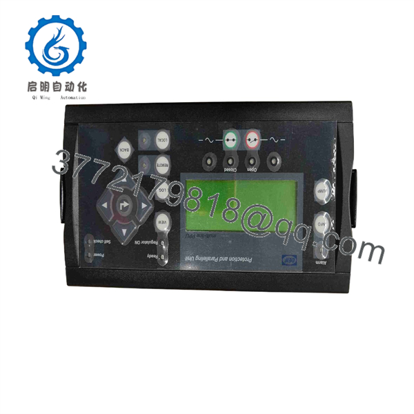
11-0018905
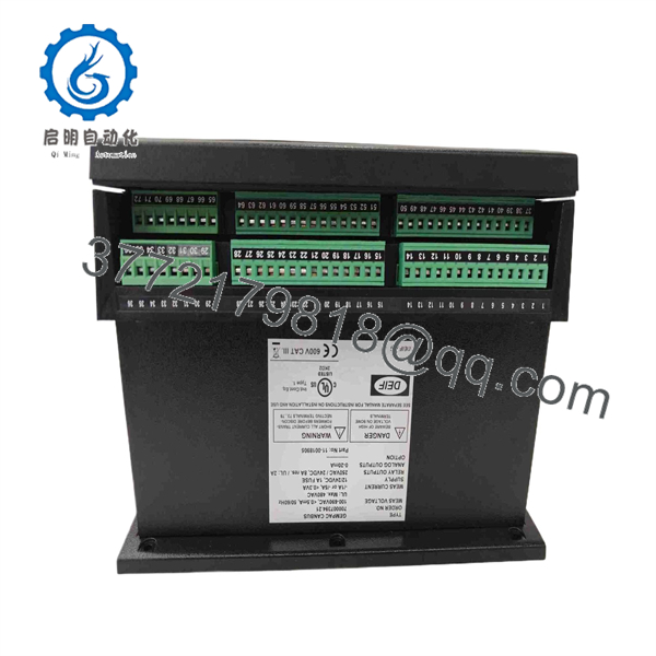
11-0018905
Installation & Configuration Guide
Stage 1 — Pre-Installation
Estimated time: 30–60 minutes
- Place the generator system in the approved maintenance state.
- Prevent automatic generator starting and isolate the associated control circuits.
- Apply LOTO to hazardous electrical sources according to the site procedure.
- Verify that generator and busbar voltage are absent before opening the control enclosure.
- Record the existing 11-0018905 part number and revision.
- Photograph all wiring, board positions, DIP-switch settings, and jumper positions.
- Record the existing CANBUS connections and rack I/O address.
- Back up the relevant DEIF/GEMPAC configuration if the system provides configuration storage.
⚠️ Do not change DIP-switch or jumper settings before recording the original configuration. These settings can affect I/O addressing and voltage measurement.
Stage 2 — Remove the Existing Unit
Estimated time: 30–60 minutes
- Confirm the generator is prevented from starting.
- Verify electrical isolation.
- Label CANBUS and control wiring before disconnection.
- Record connector orientation and cable routing.
- Photograph the SCM-A, CANBUS, and SCM-C board arrangement where applicable.
- Disconnect the wiring using appropriate ESD precautions.
- Remove the assembly from its mounting arrangement.
- Keep the original unit available until the replacement has passed functional testing.
The documented SCM-1 arrangement uses an eight-wire inter-board connection rather than treating the boards as independent backplane modules.
Stage 3 — Install the 11-0018905
Estimated time: 45–90 minutes
- Verify the replacement part number.
- Compare the replacement’s board arrangement with the removed assembly.
- Confirm the CANBUS board is installed in the correct position.
- Reproduce the recorded I/O-address DIP-switch settings.
- Reproduce the recorded generator and busbar voltage-range jumper settings.
- Reconnect the internal board interconnects.
- Reconnect external CANBUS and control wiring.
- Confirm connector seating and mechanical retention.
- Inspect for loose conductors, damaged terminals, or contamination.
- Verify grounding and shielding according to the original DEIF installation.
⚠️ Do not copy settings from another GEMPAC installation. Generator voltage, bus configuration, and I/O addressing are application-dependent.
Stage 4 — Power-On and Functional Testing
Estimated time: 60–120 minutes
- Restore control power while keeping the generator in a safe commissioning state.
- Check for controller and CANBUS diagnostic alarms.
- Confirm communication between the GEMPAC controller and connected system components.
- Verify that the configured I/O address is unique.
- Confirm generator-voltage measurement.
- Confirm busbar-voltage measurement.
- Verify phase relationships and synchronization measurements.
- Test relay outputs and associated OPR-1 functions where fitted.
- Perform a controlled synchronization test according to the generator manufacturer’s procedure.
- Verify generator start/stop and protection logic only after measurement and communication checks pass.
- Record final DIP-switch and jumper settings.
- Document the replacement part number and commissioning results.
The published SCM-1 replacement information specifically identifies the I/O address as a DIP-switch setting and the generator/busbar voltage measurement ranges as jumper-selected parameters.
FAQ
What is DEIF 11-0018905?
11-0018905 is a DEIF GEMPAC CANBUS component used within generator-control and synchronization equipment. It is also associated with the SCM-1 synchronizing/measuring architecture in available service documentation.
Is 11-0018905 a complete generator controller?
The terminology varies among secondary-market sellers. Some list it as a GEMPAC CANBUS control unit, while technical documentation identifies the corresponding CANBUS board within an assembly. Procurement should therefore compare the actual physical assembly and machine documentation, not just the commercial product title.
What communication interface does it use?
The part is specifically identified as GEMPAC CANBUS. The exact CAN bus configuration, addressing, and communication parameters should be taken from the installed DEIF/GEMPAC system documentation.
Does the module use DIP switches?
Yes, the documented architecture uses DIP switches for rack I/O addressing. The voltage measurement ranges are selected through jumpers on the SCM-C board.
Can I replace 11-0018905 with another DEIF CANBUS module?
Not automatically. The replacement must match the GEMPAC/DELOMATIC architecture, board arrangement, I/O addressing, voltage-measurement configuration, CANBUS connections, and associated relay modules.
Is 11-0018905 still available?
Secondary-market inventory currently includes new, used, and surplus examples. One current listing shows the exact model as new but sold out, while another lists used units. Availability therefore varies by supplier and condition.
What should procurement verify before ordering?
Request photographs of the actual 11-0018905 unit, including its identification label, PCB markings, connector arrangement, DIP-switch positions, and jumper configuration. Also confirm whether the application uses the architecture and whether the supplied unit includes the same board assembly.



