
 WhatsApp: +86 16626708626
 Email:
  Phone: +86 16626708626
Description
3. Key Technical Specifications
| Parameter | Value |
|---|---|
| Display Size | 7 inch widescreen TFT |
| Resolution | 1024 × 600 (WSVGA) |
| Touch Type | Projected capacitive multi-touch (PCT) |
| CPU | ARM Cortex-A9, 800 MHz |
| Memory | ~512 MB RAM, onboard flash storage |
| Operating System | Windows Embedded Compact 7 |
| Supply Voltage | 24 V DC (~0.6 A typical) |
| Power Consumption | ~14 W typical |
| Ethernet | 2 × 10/100 Mbps ports |
| Serial Interfaces | RS232, RS485 |
| Additional Interfaces | USB (host/device), CAN |
| Protocol Support | Modbus TCP/RTU, CANopen, EtherNet/IP (via CODESYS) |
| Mounting | Flush panel mount |
| Protection Rating | IP65 (front) |
| Operating Temperature | 0 to +50 °C |
4. Product Introduction
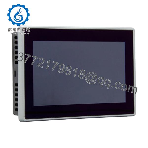
The Eaton XV-303-70-CE0-A00-1E is a 7-inch XV300 series HMI panel with integrated PLC capability using CODESYS. It is designed for machine-level control where visualization and logic execution are combined into a single device.
In real installations, this unit replaces separate PLC + HMI architectures in compact systems. Dual Ethernet ports allow segregation between control and plant networks, while native support for SmartWire-DT and CAN simplifies distributed I/O integration.
5. Installation & Configuration Guide
Stage 1: Pre-Installation Preparation (Estimated: 10 minutes)
- ⚠️ Safety First: Notify operations, stop machine, apply lockout/tagout, wait 5 minutes.
- Tools Required: ESD strap, PH1 screwdriver, multimeter, wire labels, smartphone.
- Data Backup:
- Export CODESYS project and HMI visualization
- Record IP addresses (both Ethernet ports)
- Photograph wiring and communication ports
Stage 2: Removing the Old Module (Estimated: 5–10 minutes)
- Remove rear mounting clamps.
- Label Ethernet (Port 1 vs Port 2 — critical).
- Disconnect power and communication cables.
- Push unit out of panel cutout.
- Inspect gasket and mounting surface.
⚠️ Note: Do not discard the old unit until system is fully operational.
Stage 3: Installing the New Module (Estimated: 10 minutes)
- Wear ESD protection.
- Confirm exact model (XV-303 variants differ by interface and firmware).
- Insert panel into cutout; ensure gasket sealing.
- Tighten clamps evenly (avoid panel warping).
- Reconnect:
- 24 V DC supply
- Ethernet (maintain port roles: control vs plant network)
- Serial/CAN wiring
Self-Checklist:
- Correct Ethernet port mapping
- Power polarity verified
- Panel seated evenly
- All connectors secure
Stage 4: Power-On & Testing (Estimated: 10–15 minutes)
Pre-Power Check:
- Measure 24 V DC rail stability
Power-On Steps:
- Power up HMI only.
- Observe boot (Windows CE + runtime).
- Connect via CODESYS engineering tool.
- Verify:
- IP addresses (both NICs)
- PLC runtime state
- Download project if required.
- Test:
- Touchscreen response
- Fieldbus communication
- PLC logic execution
⚠️ Troubleshooting Note:
- No communication → check dual Ethernet routing
- PLC not running → runtime mismatch
- Screen responsive but no I/O → fieldbus config issue

- XV-303-70-CE0-A00-1E
6. Frequently Asked Questions (FAQ)
Q1: Can this unit replace an XV100 series HMI directly?
No. XV300 uses a different software stack (Visual Designer + CODESYS 3). XV100 projects (Galileo/XSoft-CoDeSys 2) are not directly compatible. Expect conversion work.
Q2: Is this a true PLC or just an HMI?
It’s both. This unit runs a full CODESYS PLC runtime. In smaller machines, it can eliminate the need for a separate PLC.
Q3: Can I hot-swap this panel?
No. Always power down. These units are sensitive to voltage spikes during insertion/removal.
Q4: What’s the advantage of dual Ethernet ports?
Network segregation. One port for machine-level devices, one for plant/SCADA. This reduces broadcast traffic and avoids comms congestion.
Q5: Is this model still in production?
XV300 is still supported, but lead times can be long depending on configuration. Many buyers rely on surplus stock for immediate replacement.
Q6: Will my program survive if the unit fails?
No. Logic and visualization are stored locally. Without a backup, recovery is difficult. Always maintain project archives.
Q7: Why do some units fail to boot after replacement?
Most cases I’ve seen are due to corrupted SD/flash or firmware mismatch. Not hardware failure.
SOP Quality Transparency (Inspection & Testing Process)
1. Inbound Inspection & Traceability
- Verified against Eaton catalog data and labeling
- Serial number and product code validated
- Visual inspection: no scratches, no LCD defects, no connector oxidation
- Accessories checked (mounting hardware, seals)
2. Live Functional Testing
- Tested using regulated 24 V DC industrial supply
- Boot cycle monitored (Windows CE + runtime)
- Dual Ethernet tested independently (ping + Modbus TCP simulation)
- Serial ports tested via loopback
- CAN communication verified using test node
- Touchscreen tested across full surface
- 24-hour continuous operation with thermal monitoring
3. Electrical Parameter Testing
- Insulation resistance >10 MΩ @ 500 V
- Ground continuity verified
- Power draw measured under load
4. Firmware & Configuration Verification
- Firmware/runtime version recorded
- Default communication parameters documented
- Ethernet port roles verified
5. Final QC & Packaging
- QC sign-off with trace ID
- Anti-static ESD packaging
- Foam-protected heavy-duty carton
- QC Passed label applied
Test reports, boot videos, and inspection photos available upon request.
Technical Pitfalls & Survival Guide
❗ 1. CODESYS Version Mismatch
This is a frequent issue. A project built in a newer CODESYS version may not run on older runtime firmware.
Avoidance: Match runtime version before deployment.
I’ve seen machines sit idle for two days because of this.
❗ 2. Dual Ethernet Misconfiguration
Engineers often mix up the two ports.
Avoidance: Document which port connects to which network before removal.
Wrong mapping = total loss of comms.
❗ 3. Project Migration from XV100
This is not plug-and-play.
Avoidance: Plan engineering time for conversion.
Don’t promise production you’ll swap it in 30 minutes — it won’t happen.
❗ 4. Power Supply Stability
These units draw more current than older XV100 panels.
Avoidance: Verify supply capacity with 20% margin.
Voltage dips cause random reboots — hard to trace.
❗ 5. ESD Damage During Handling
Capacitive touch panels are sensitive.
Avoidance: Use proper grounding.
I’ve personally seen a panel fail immediately after installation due to static.


