
 WhatsApp: +86 16626708626
 Email:
  Phone: +86 16626708626
Description
Key Technical Specifications
| Parameter | Value |
|---|---|
| Product Model | FBMSSW |
| Manufacturer | Foxboro (Invensys / Schneider Electric) |
| System Platform | Foxboro I/A Series DCS |
| Product Type | Specialized Servo Control Fieldbus Module |
| Primary Application | Hydraulic and pneumatic servo actuator control |
| Feedback Interface | LVDT position feedback |
| LVDT Excitation Frequency | 1 kHz (reported specification, verify against installed documentation) |
| Servo Output | ±21 mA current drive output |
| Auxiliary Power Supply | ±15 V DC external supply |
| Control Function | Closed-loop servo positioning |
| Fieldbus Interface | Foxboro I/A Series Fieldbus |
| Communication Architecture | 2 Mbps I/A Series Fieldbus |
| Input Type | LVDT differential feedback signal |
| Output Type | Bipolar servo current output |
| Mounting | Foxboro I/A Series FBM rack |
| Application Devices | Servo valves, hydraulic actuators, precision position control systems |
| Configuration Method | Foxboro I/A Series engineering tools |
| Operating Temperature | Depends on installed I/A Series hardware environment |
| Storage Temperature | Depends on storage conditions |
| Humidity | Non-condensing industrial environment |
| Lifecycle Status | Legacy / Obsolete hardware |
Technical Note:
FBMSSW is not a standard analog I/O module. It combines LVDT signal conditioning and servo drive functions in one dedicated control interface. Available technical listings associate FBMSSW with servo valve applications, LVDT feedback processing, ±21 mA servo output, and ±15 V DC auxiliary power. Verify exact electrical parameters against the installed Foxboro documentation before replacement.
Product Introduction
The Foxboro FBMSSW is a specialized I/A Series Fieldbus Module designed for closed-loop servo control applications. It interfaces with LVDT-equipped hydraulic or pneumatic actuators by processing position feedback signals and generating proportional servo drive output commands.
Unlike general-purpose FBM analog modules, FBMSSW performs dedicated actuator positioning functions. It is typically found in legacy process control applications where accurate valve stroke control and existing servo hardware must be maintained.
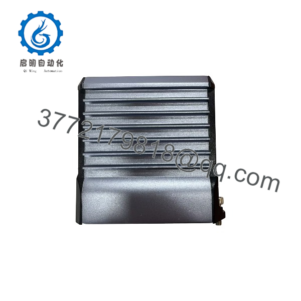
FBMSSW
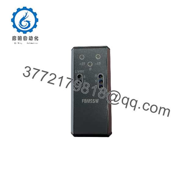
FBMSSW
Installation & Configuration Guide
Stage 1: Pre-Installation Preparation (Approx. 15 minutes)
⚠️ Safety First
- Notify operations before removing the FBMSSW module.
- Confirm the controlled actuator or valve can be taken offline.
- Place the process in a safe operating condition.
- Apply lockout/tagout procedures if cabinet power isolation is required.
- Wait at least 5 minutes after power removal before handling the module.
Tools Required
- ESD wrist strap
- PH1 screwdriver
- Digital multimeter
- Wire labels
- Smartphone for photos
- Loop calibrator or actuator simulator (recommended)
Data Backup
Before removal:
- Record:
- FBMSSW module location
- Hardware revision
- Associated servo loop tag
- Actuator model
- LVDT wiring configuration
- Photograph:
- Module position
- Terminal wiring
- Shield grounding
- LVDT connections
- Document:
- Servo calibration parameters
- Output limits
- Control loop settings
Stage 2: Removing the Old Module (Approx. 10 minutes)
Steps
- Open the Foxboro I/A Series cabinet.
- Confirm the correct FBMSSW location.
- Label all actuator and feedback wiring.
- Disconnect wiring carefully.
- Release module retaining tabs.
- Pull the FBMSSW straight from the baseplate.
- Inspect:
- Backplane connector pins
- Module contacts
- Connector condition
- Dust contamination
⚠️ Note:
Keep the original FBMSSW until the replacement servo loop passes calibration. Servo modules directly affect actuator position, and incorrect replacement can move equipment unexpectedly.
Stage 3: Installing the New Module (Approx. 20 minutes)
Steps
- Wear an ESD strap before handling the replacement module.
- Verify:
- Model number: FBMSSW
- Compatible Foxboro I/A Series rack
- Correct servo application
- Correct LVDT wiring arrangement
- Configuration Clone (Critical):
- Record original calibration values.
- Match servo output configuration.
- Verify LVDT excitation wiring.
- Confirm feedback polarity.
- Verify actuator stroke direction.
- Check shielding and grounding.
- Insert the module into the FBM rack.
- Lock the module securely.
- Reconnect field wiring.
Self-Checklist
- FBMSSW model confirmed
- LVDT wiring matched
- Servo output wiring checked
- Shield grounding verified
- Module fully seated
Stage 4: Power-On & Testing (Approx. 30 minutes)
Pre-Power Check
- Verify module power supply.
- Confirm LVDT excitation wiring.
- Check servo actuator connections.
- Verify no short circuits exist.
Power-On Steps
- Restore cabinet power.
- Check FBMSSW status indication.
- Verify Fieldbus communication.
- Confirm module status in Foxboro engineering tools.
- Verify LVDT feedback signal.
- Perform actuator stroke test.
- Calibrate zero and span if required.
- Return loop to automatic control after verification.
⚠️ Troubleshooting Note
- If feedback is unstable, check LVDT wiring polarity and shielding.
- If actuator moves in the wrong direction, verify servo output polarity.
- If communication fails, check Fieldbus connection and module configuration.
Frequently Asked Questions (FAQ)
Q1: What is the Foxboro FBMSSW used for?
FBMSSW is designed for servo control applications where the DCS must control a hydraulic or pneumatic actuator using LVDT position feedback.
It is not a replacement for standard analog output modules such as FBM237 or FBM218.
Q2: Is FBMSSW compatible with Foxboro I/A Series systems?
Yes, FBMSSW belongs to the Foxboro I/A Series FBM family. However, verify the installed controller generation, software revision, and servo application configuration before replacement.
Q3: Is the FBMSSW obsolete?
Yes. FBMSSW is considered legacy Foxboro I/A Series hardware. Many plants continue maintaining I/A Series systems, so replacement demand remains for installed equipment support.
Availability depends on New Original, New Surplus, and tested refurbished inventory.
Q4: Can I replace FBMSSW with a normal analog output module?
No.
A standard analog output module only generates a current signal. FBMSSW provides:
- LVDT excitation
- Position feedback processing
- Servo current control
Replacing it with a normal AO module would require major control redesign and additional hardware.
Q5: Can FBMSSW be hot-swapped?
Do not assume it can be removed under power.
Although some Foxboro FBM architectures support online replacement procedures, servo applications require checking:
- Redundancy design
- Actuator safety requirements
- Site maintenance procedure
before removing an active module.
Q6: Will replacing FBMSSW erase my servo calibration?
The physical replacement does not normally erase the Foxboro control database.
However, verify:
- Servo loop parameters
- LVDT calibration values
- Output limits
- Channel assignments
before placing the actuator back into service.
Q7: Why is surplus FBMSSW cheaper than OEM pricing?
Legacy DCS modules are commonly sourced from:
- Plant spare inventory
- System upgrade projects
- Equipment retirement programs
- Excess maintenance stock
Condition should always be identified clearly:
- New Original / New Surplus: Unused inventory.
- Factory Sealed: Original packaging when available.
- Refurbished (tested): Function-tested before shipment.
Q8: What inspection process should be completed before installing a surplus FBMSSW?
Inbound Inspection & Traceability
- Verify supplier records.
- Confirm FBMSSW identification label.
- Check serial information.
- Inspect housing condition.
- Confirm no corrosion, repair marks, or physical damage.
Live Functional Testing
Test Environment:
- Genuine Foxboro I/A Series FBM test rack.
Testing steps:
- Power-up verification.
- Fieldbus communication check.
- LVDT simulator connection test.
- Servo output current verification.
- Continuous operation monitoring.
- Test report generation.
Electrical Parameter Testing
- Insulation resistance test using 500 V Megger where applicable.
- Ground continuity check.
- Servo output verification.
Firmware & Configuration Verification
- Record hardware revision.
- Document module identification.
- Save calibration information.
- Photograph labels and connectors.
Final QC & Packaging
- QC inspector sign-off.
- Anti-static ESD bagging.
- Bubble wrap protection.
- Heavy-duty corrugated boxing.
- QC Passed label with inspection date.
Q9: What are common FBMSSW replacement mistakes?
❗ The most common mistake is treating FBMSSW as a normal I/O replacement.
Common issues include:
- Installing an analog output module instead.
- Incorrect LVDT wiring polarity.
- Missing shield grounding.
- Losing servo calibration data.
- Testing actuator movement without process coordination.
For servo control hardware, document the existing loop before removal. A few minutes spent recording wiring and parameters can prevent hours of commissioning work.



