
 WhatsApp: +86 16626708626
 Email:
  Phone: +86 16626708626
Description
Key Technical Specifications
- Application: GE turbine / drive control systems
- Board Type: Industrial control circuit board
- Functionality: Signal conditioning, control logic processing
- Input Types: Analog and discrete signals (system dependent)
- Output Types: Control and feedback signals to system modules
- Interface: Proprietary GE backplane or wired harness connection
- Power Supply: Backplane-powered (typically 5 V / 24 V internal rails)
- Operating Temperature: 0°C to +60°C (control cabinet standard)
- Construction: Multi-layer PCB with industrial-grade components
- Mounting: Rack or panel-mounted (system dependent)
- Weight: Approx. 0.5–1.2 kg
4. Product Introduction
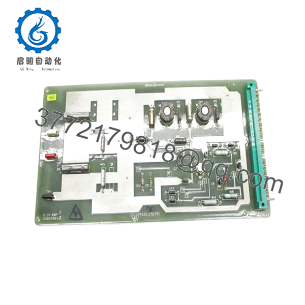
The GE 125D5788G2 is an industrial control circuit board used in GE turbine and drive control systems, handling signal processing and control logic functions within the system architecture. It integrates into GE proprietary racks or panel assemblies depending on the installation.
In real plant environments, this board typically shows up in legacy GE control platforms where system upgrades are deferred due to cost or downtime risk. Engineers keep these units in inventory because a failed board can take a turbine offline immediately, and lead times for replacements are unpredictable.
- 125D5788G2

- 125D5788G2
5. Installation & Configuration Guide
Stage 1: Pre-Installation Preparation (Estimated Time: 10–15 min)
- ⚠️ Safety First:
Shut down the system, isolate all power sources, apply lockout/tagout, and wait at least 5 minutes. - Tools Required:
ESD wrist strap, PH1 screwdriver, Fluke 115 multimeter, labeling tape, smartphone. - Data Backup:
- Photograph the installed board and wiring
- Record connector positions and cable routing
- Note system alarms or faults before shutdown
Stage 2: Removing the Old Module (Estimated Time: 5–10 min)
- Open cabinet and locate the board position.
- Identify all connectors and label them clearly.
- Disconnect cables gently — no prying.
- Remove mounting screws or release clips.
- Pull the board straight out to avoid connector damage.
- Inspect connectors for oxidation or bent pins.
- ⚠️ Note: Keep the original board for reference. It’s your baseline if something doesn’t behave after replacement.
Stage 3: Installing the New Module (Estimated Time: 5–10 min)
- Apply ESD protection before handling.
- Verify part number: 125D5788G2 (watch for similar G1/G3 variants).
- Configuration Check (Critical):
- Compare jumper settings or component options
- Match any field modifications from the original board
- Install the board into the same slot or mounting location.
- Secure with screws/clips.
- Reconnect all cables exactly as labeled.
- Self-Checklist:
[ ] Model verified
[ ] Wiring matched
[ ] Board fully seated
[ ] No loose connectors
Stage 4: Power-On & Testing (Estimated Time: 10–15 min)
- Pre-Power Check:
Measure supply rails for shorts before energizing. - Power-On Steps:
- Energize control power only.
- Observe system indicators and alarms.
- Verify communication with associated modules.
- Check signal readings via HMI or diagnostic interface.
- Perform functional test (without loading the turbine initially).
- ⚠️ Troubleshooting Note:
- No response → check connector seating and wiring order
- Intermittent signals → inspect grounding and shielding
- Immediate fault → suspect wrong revision or configuration mismatch
6. Frequently Asked Questions (FAQ)
Q1: Can I hot-swap the GE 125D5788G2?
No. These legacy GE boards are not designed for hot-swapping. You risk damaging the backplane or adjacent circuitry. Always power down.
Q2: Is this model obsolete?
Yes. This is a legacy GE control board with no current OEM production. Availability depends on surplus inventory.
Q3: Are G1, G2, and G3 revisions interchangeable?
Not safely. GE often changed component layouts or signal paths between revisions. I’ve seen “almost identical” boards cause intermittent faults. Match the exact suffix.
Q4: Will replacing this board affect system logic?
No stored logic on the board itself. However, it directly affects signal processing. After replacement, always verify calibration and signal scaling.
Q5: Why do these boards fail in the field?
Typical causes:
- Thermal cycling in cabinets
- Electrolytic capacitor aging (10–15 years lifecycle)
- Dust and conductive contamination
Q6: Why is pricing inconsistent across suppliers?
Because supply is entirely secondary market. Some units are pulled from decommissioned systems, others are unused surplus. Condition verification matters more than price.
Q7: What’s the most common installation mistake?
❗ Miswiring connectors after removal.
It sounds basic, but under outage pressure, cables get swapped. Take photos before touching anything. It saves hours of fault tracing.


