
 WhatsApp: +86 16626708626
 Email:
  Phone: +86 16626708626
Description
3. Key Technical Specifications
- Application: GE industrial control systems (turbine / drive / auxiliary control)
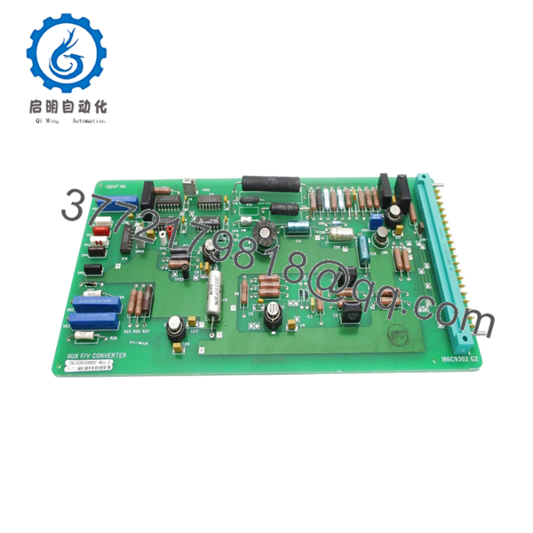
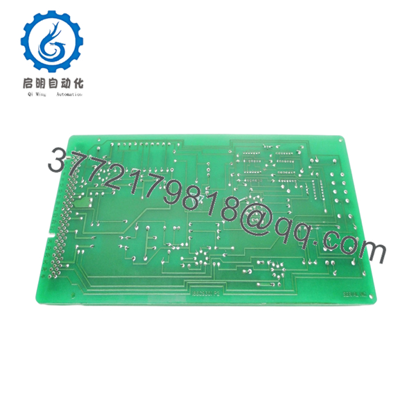
- Board Type: Control and interface PCB
- Revision: Rev. 3 (updated hardware iteration)
- Input Types: Analog and discrete signals (system dependent)
- Output Types: Control signals to system logic layers
- Interface: Proprietary GE connector/backplane
- Power Supply: Backplane-powered (5 V / 24 V typical internal rails)
- Operating Temperature: 0°C to +60°C (cabinet conditions)
- Construction: Multi-layer PCB, through-hole + SMD components
- Mounting: Rack-mounted or panel-mounted (application dependent)
- Dimensions: Standard GE board footprint (~12 x 8 in class)
- Weight: ~0.6–1.2 kg
4. Product Introduction
The GE 186C9303G0002 REV. 3 is a control PCB used in GE industrial control architectures, typically handling signal interfacing and logic processing within turbine or auxiliary control systems. The “REV. 3” designation indicates a later hardware revision with incremental design updates.
In real installations, boards like this are retained for long-life assets where system replacement is not practical. Engineers rely on exact revision matching because even minor hardware changes between revisions can affect signal timing or connector behavior.

- 186C9303G0002 REV. 3
5. Installation & Configuration Guide
Stage 1: Pre-Installation Preparation (Estimated Time: 10–15 min)
- ⚠️ Safety First:
Shut down the system, isolate all energy sources, apply lockout/tagout, and wait at least 5 minutes. - Tools Required:
ESD wrist strap, PH1 screwdriver, Fluke 115 multimeter, labeling tags, smartphone. - Data Backup:
- Photograph board location and wiring
- Record connector orientation and cable routing
- Capture any existing alarms or abnormal readings
Stage 2: Removing the Old Module (Estimated Time: 5–10 min)
- Open the cabinet and locate the board.
- Label every connector before removal.
- Disconnect cables carefully — avoid pulling on wires.
- Remove retaining screws or clips.
- Pull the board straight out to protect connectors.
- Inspect mating connectors for bent pins or contamination.
- ⚠️ Note: Keep the old board accessible. It’s your reference if anything behaves differently after replacement.
Stage 3: Installing the New Module (Estimated Time: 5–10 min)
- Wear ESD protection before handling.
- Confirm model: 1186C9303G0002 REV. 3 (match revision exactly).
- Configuration Clone (Critical):
- Compare jumper settings or hardware options
- Replicate any non-default configurations
- Insert the board into the correct slot or mounting position.
- Secure with screws/clips.
- Reconnect cables exactly as labeled.
- Self-Checklist:
[ ] Revision matches (REV. 3)
[ ] Wiring correct
[ ] Fully seated
[ ] No connector damage
Stage 4: Power-On & Testing (Estimated Time: 10–15 min)
- Pre-Power Check:
Measure supply rails for shorts using a multimeter. - Power-On Steps:
- Energize control power only.
- Observe system indicators and alarms.
- Verify communication with related modules.
- Check signal values through HMI or diagnostic interface.
- Perform controlled functional test before returning to full operation.
- ⚠️ Troubleshooting Note:
- Immediate fault → likely revision or configuration mismatch
- No signal response → check connector orientation
- Intermittent issues → inspect grounding and shielding
6. Frequently Asked Questions (FAQ)
Q1: Can this board be hot-swapped?
No. These GE legacy boards are not designed for live insertion. You risk damaging the system backplane. Always power down.
Q2: What does “REV. 3” actually mean?
It indicates a hardware revision. GE typically introduced small design updates across revisions—component substitutions, layout tweaks, or signal conditioning changes.
From experience, even minor revisions can cause compatibility issues in older systems.
Q3: Is this interchangeable with earlier revisions (REV.1 / REV.2)?
Not guaranteed. I’ve seen cases where a REV.3 board introduced slight timing differences that caused unstable signals. Always match the exact revision unless you’ve verified compatibility with GE documentation.
Q4: Is this model still manufactured?
No. This is a legacy GE part. Availability depends on surplus stock or reclaimed inventory.
Q5: Will replacing this board affect system logic?
The board itself typically does not store logic, but it directly affects signal processing. After replacement, verify scaling, calibration, and signal integrity.
Q6: What’s the most common failure mode?
- Aging capacitors
- Thermal stress from cabinet heat cycles
- Connector oxidation
After 10–15 years, failures become more frequent.
Q7: What’s the biggest mistake during replacement?
❗ Mixing up connectors or assuming similar boards are interchangeable.
I’ve seen engineers install a visually identical board with a different revision—system booted, but signals were unstable for hours. Always verify part number and revision before installation.


