
 WhatsApp: +86 16626708626
 Email:
  Phone: +86 16626708626
Description
3. Key Technical Specifications
| Parameter | Value |
|---|---|
| Model String Decoded | 369 = Series / HI = Enhanced display / R = Rack mount / 0 = No CTs / 0 = No analog output / 0 = No RTDs / 0 = No device net / E = Enhanced firmware |
| Control Power | 120–240 VAC, 50/60 Hz (also accepts 125–250 VDC) |
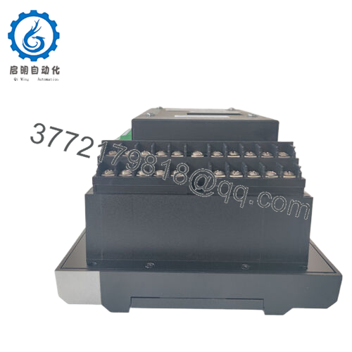
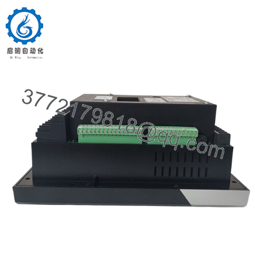
| Display | Enhanced backlit LCD (16 lines x 40 characters) |
| Mounting | Rack mount (19″ rack compatible) |
| CT Inputs | None included — external CTs required (user-supplied) |
| Analog Outputs | 0 (option not populated) |
| RTD Inputs | 0 (option not populated) |
| Communications | RS-485 Modbus RTU (standard) |
| Fieldbus Options | None on this variant (no DeviceNet, no Profibus) |
| Firmware | Enhanced version (E suffix) — includes advanced protection algorithms |
| Protection Functions | Overload, short circuit, ground fault, phase unbalance, undercurrent, jam, stall, starts per hour |
| Metering | Current, voltage, power, energy, demand, thermal capacity |
| Operating Temp | –40°C to +60°C (–40°F to +140°F) |
| Dimensions (HxWxD) | 7.0″ x 6.9″ x 6.5″ (178 x 175 x 165 mm) |
| Weight | 5.5 lbs (2.5 kg) |
4. Product Introduction
The GE Multilin 369-HI-R-0-0-0-0-E is a motor management relay designed for critical motor protection in industrial plants. This is the enhanced display version with rack mount form factor, running on 120-240VAC control power. No CTs, no RTDs, no analog outputs — just the core relay with RS-485 Modbus.
The 369 series uses thermal modeling to protect motors from overload, stall, and excessive starts. It meters real current, calculates thermal capacity used, and trips before winding damage occurs. Field engineers choose this relay because it logs events, stores trip records, and works without a PLC. This specific variant ships new surplus — factory-sealed, never installed.
- 369-HI-R-0-0-0-0-E
5. Troubleshooting Quick Reference
| Symptom | Possible Cause | Relevance to this Part | Quick Check Method | Recommendation |
|---|---|---|---|---|
| No display, relay dead | Missing control power or blown internal fuse | ❌ Low | Measure across L1 and N terminals (expect 120-240VAC) | Check upstream breaker and control transformer first |
| Display shows “Phase Rotation” fault | Incorrect phase sequence at CT inputs | ❌ Low | Swap any two motor leads at the contactor | Relay is working correctly. Fix field wiring. |
| Display shows “Ground Fault” but no actual fault | CT wiring error or external CT mismatch | ⚠️ Medium | Verify ground CT is installed and wired to terminals G1/G2 | If no ground CT installed, disable ground fault protection in setpoints |
| Relay trips on “Overload” with low motor current | CT ratio programmed incorrectly | ✅ High | Compare setpoint “CT Primary” against actual CT nameplate | Enter correct CT ratio. This is the #1 field mistake. |
| Cannot communicate via Modbus | Wrong address, baud rate, or parity | ⚠️ Medium | Check setpoints S6: Comm Address, S7: Baud Rate, S8: Parity | Default is address 1, 9600, 8/N/1. Verify wiring to terminals C1/C2. |
| Display backlight works but no text | Display driver failure | ✅ High | Cycle power. If still blank, press any arrow key to wake display | Replace relay. Display failure is known issue on early 369 units. |
| Relay trips instantly on start command | Phase CT missing or wired backward | ❌ Low | Verify all three phase CTs are installed and wired to terminals C1-C6 | Check for open CT circuit — never leave CT secondary open. Dangerous voltage will appear. |
| “RTD” alarm but no RTDs installed | RTD option not populated but setpoints enable it | ⚠️ Medium | Navigate to setpoint S4: RTD Enable | Set to “Disabled”. This variant has no RTD inputs (third 0 in model string). |
Still stuck? Enter setpoint mode (press Menu, then Enter). Write down all S-setpoints (S1 through S99). Email the list to our tech support. We’ll identify misconfigurations within one business day.
6. Frequently Asked Questions (FAQ)
Q1: What do the zeros in the model number 369-HI-R-0-0-0-0-E mean?
Each zero is an option not populated:
- First 0 = No CTs (you supply external CTs)
- Second 0 = No analog output (4-20mA not available)
- Third 0 = No RTD inputs (no thermocouple or RTD cards)
- Fourth 0 = No DeviceNet
- E = Enhanced firmware (standard on later units)
This is the base functional relay with Modbus only. Most plants prefer this because they supply their own CTs and use Modbus to the PLC.
Q2: What external CTs do I need?
You need three phase CTs (one per phase) and optionally one ground CT. CT primary rating must match your motor full load amps. Example: for a 200A motor, use 200:5 CTs. Set the CT Primary setpoint to 200. Secondary is always 5A. Do NOT use 1A secondary CTs — this relay expects 5A.
Q3: Can I use this relay on a 4800V medium voltage motor?
Yes, but you need external CTs and PTs (potential transformers). The 369 only sees 5A from CTs and 120V from PTs. The MV gear provides the isolation. This is standard practice in pump stations and compressor stations.
Q4: Does this relay retain settings if control power is lost?
Yes. All setpoints are stored in non-volatile EEPROM. No battery backup required. When power returns, the relay resumes monitoring immediately with the last saved configuration.
Q5: Is this relay hot-swappable in a live panel?
No. Kill control power before removing or installing the relay. The CT inputs are not designed for live disconnection — opening CT secondary under load creates lethal voltages (thousands of volts). Follow your plant’s LOTO procedure.
Q6: Why is this cheaper than buying from GE directly?
This is new surplus stock from a project cancellation. Factory-sealed, never installed, original packaging. GE’s factory lead time on 369 relays is currently 16-20 weeks. We have this unit on the shelf ready to ship. Our 1-year warranty replaces GE’s standard 2-year — but you get it today, not in five months.
Q7: Can I upgrade this relay to add RTD inputs later?
No. RTDs require a hardware card that is not present (third zero in model string). You would need a different variant: 369-HI-R-0-0-1-0-E for six RTDs. This unit cannot be field-upgraded.
Q8: What software do I need to configure this relay?
You can configure entirely from the front keypad — no software required. For remote configuration and data logging, GE offers EnerVista 369 software (free download from GE website). You will need a RS-485 to USB converter (not included).
Q9: What is the warranty period and process?
1 year from invoice. If the relay fails during normal operation, we cross-ship a replacement within 24 hours. You return the failed unit in the same box. No restocking fee. Exclusions: lightning strikes, water damage, incorrect wiring, or CT secondary open-circuit events.


