
 WhatsApp: +86 16626708626
 Email:
  Phone: +86 16626708626
Description
3. Key Technical Specifications
- Control Power: 50–300 VDC or 60–265 VAC, 50/60 Hz, nominal 20 VA (max 65 VA)
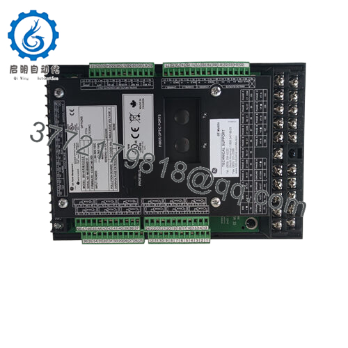
- RTD Inputs: 12 built-in, 3-wire, software selectable (100 Ω Pt, 120 Ω Ni, 10 Ω Cu, etc.), range –40 to +200 °C
- Metering Package (M option): Voltage, power (kW, kvar, kVA, PF, Hz, MWh), 4 isolated analog outputs (0-1/0-20/4-20 mA)
- Communications: Front RS232, three rear RS485 (Modbus RTU), Ethernet (E option, Modbus TCP/IP)
- Output Relays: 4 programmable (Trip, Alarm, Aux1, Aux2), 8 A resistive at 250 VAC
- Digital Inputs: 6 optically isolated
- Operating Temperature: –40 °C to +60 °C (some sources list up to +85 °C short-term per IEC)
- Storage Temperature: –40 °C to +80 °C
- Harsh Environment Option (H): Conformal coating for corrosive conditions
- Enhanced Faceplate & Diagnostics (E in this context)
- Dimensions (approx.): 29.6 cm H × 10.7 cm W × 20.5 cm D
- Weight (approx.): 4.5 kg (10 lb)
- IP Rating: IP50X
- Mounting: Panel mount, non-drawout design
4. Product Introduction
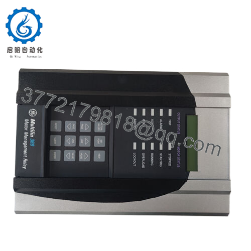
The GE 369-HI-R-M-0-0-H-E is a digital motor management relay from the GE Multilin 369 series. It provides integrated protection, control, and monitoring for three-phase medium-sized AC motors and their driven equipment in industrial applications such as pumps, fans, compressors, and conveyors.
This configuration includes high-range control power, 12 RTD inputs for stator and bearing temperature monitoring, the full metering package with voltage and power measurements, the harsh environment conformal coating, and Ethernet communications. Engineers select it for its ability to learn motor parameters (inrush, acceleration, cooling rates) and apply FlexCurve overload characteristics, giving tighter protection than generic thermal models while supporting field firmware upgrades and EnerVista setup software.

- 369-HI-R-M-0-0-H-E
5. Installation & Configuration Guide
Stage 1: Pre-Installation Preparation (15–20 minutes) ⚠️ Safety First: Notify operations, schedule controlled downtime, verify motor is stopped and isolated, apply lockout/tagout on the motor starter and control power, then wait 5 minutes for capacitors to discharge. Tools Required: Grounded ESD wrist strap, PH1 or PH2 screwdriver, digital multimeter, wire labels, smartphone for photos, laptop with EnerVista 369 Setup software. Data Backup: Connect via front RS232 or Ethernet, upload all setpoints and logic to a file, record learned motor data (acceleration time, cool times, etc.), photograph the existing faceplate, all DIP/jumper settings if any, and every terminal block wiring layout.
Stage 2: Removing the Old Module (5–10 minutes)
- Remove the front bezel screws if present and carefully detach the display module.
- Label every wire and terminal point before disconnection — do not rely on memory.
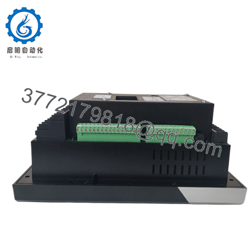
- Disconnect all CT, PT (if metered), RTD, control power, and I/O wiring without forcing connectors.
- Release the panel mounting clips or screws and withdraw the relay straight out to avoid damaging backplane or terminal pins.
- Inspect the panel cutout and wiring for corrosion, loose terminals, or bent pins. ⚠️ Note: Keep the old relay untouched until the new unit runs without issues for at least one full start-stop cycle.
Stage 3: Installing the New Module (10–15 minutes)
- Verify the new relay label exactly matches 369-HI-R-M-0-0-H-E and inspect for shipping damage.
- Configuration Clone (Crucial): Set any internal jumpers or switches to match the photographed old unit. Replicate all RTD type selections and analog output ranges later in software.
- Slide the relay into the panel cutout and secure the mounting hardware firmly.
- Reconnect all wiring exactly as labeled, applying correct torque to terminal screws. Self-Checklist: [ ] Model and options match, [ ] All wiring restored and tightened, [ ] Mounting secure, [ ] No loose strands.
Stage 4: Power-On & Testing (10–20 minutes) Pre-Power Check: Use a multimeter to confirm no shorts on the control power rails and verify expected voltage levels. Power-On Steps:
- Energize only the control power to the relay (keep motor starter isolated).
- Observe the front LEDs and LCD: Green “Healthy” or “Running” status is expected; any solid red “Trip” or “Service” requires immediate investigation.
- Connect EnerVista software via RS232 or Ethernet, confirm firmware version, and download the saved setpoint file.
- Verify all actual values (currents, RTD temps, voltages if applicable) read correctly with the motor still offline.
- Perform a dry I/O test: Force trip and alarm relays, check analog outputs, confirm RTD readings. ⚠️ Troubleshooting Note: Solid red ERR or “Relay Not Ready” often points to control power quality or firmware mismatch. No Ethernet comms usually traces to IP settings or cable/port issues. If the relay trips immediately on power-up, double-check CT polarity and ground fault settings.
Total typical swap time for an experienced technician: under 60 minutes, including testing.
6. Frequently Asked Questions (FAQ)
Can this module be hot-swapped under power? No. The 369 is a non-drawout design. Removing or inserting it while powered risks damaging the backplane or causing unintended trips. Always remove control power first.
Is the 369-HI-R-M-0-0-H-E obsolete, and are the units genuinely new? Yes, GE Vernova has discontinued the 369 series with the 859 as the recommended replacement. The units offered here are new surplus — factory original stock that was never installed. They come with full test documentation and a 1-year warranty from the date of shipment. Verify current firmware on the label or in Actual Values after installation.
What is the direct replacement if this exact model is out of stock? The GE Multilin 859 Motor Protection Relay is the current platform. Migration requires new wiring adapters in most cases and setpoint conversion using the provided tools. Contact the OEM or an experienced integrator for a full upgrade assessment to avoid extended downtime.
Will I lose my programming logic and learned motor data when I pull the old CPU/relay? No, if you upload the complete setpoint file and learned data parameters via EnerVista before removal. The new relay accepts the file directly. However, some learned values (such as thermal capacity during the last start) reset and rebuild over the first few runs.
Why is the price lower than current OEM list price? Because this is new surplus inventory rather than freshly manufactured product. All units undergo full functional testing on a 369 simulation rack, insulation resistance checks, and communication verification before shipment. Test reports and photos are available on request.
Does the Ethernet option (E) support modern cybersecurity requirements? The built-in Modbus TCP/IP on the E option provides basic connectivity but lacks the advanced security features found in newer relays such as the 859. Use it behind a secure industrial firewall and avoid direct exposure to corporate networks. Firmware upgrades are still possible for bug fixes.
How many RTDs can I actually monitor with the R option? You get 12 independent 3-wire RTD inputs built into the relay. Each can be assigned to stator, bearing, ambient, or driven equipment with individual alarm and trip thresholds plus voting logic. RTD type is selectable per channel in the software.


