
 WhatsApp: +86 16626708626
 Email:
  Phone: +86 16626708626
Description
3. Key Technical Specifications
| Parameter | Value |
|---|---|
| Product Type | Excitation Control PCB |
| Application | Generator excitation / drive control systems |
| System Compatibility | GE EX2000 and legacy excitation platforms |
| Signal Type | Mixed analog and digital control signals |
| Communication | Backplane / proprietary GE interface |
| Power Supply | Via system rack/backplane |
| Operating Temperature | 0°C to +60°C (typical cabinet environment) |
| Storage Temperature | −40°C to +85°C |
| Humidity | 5–95% non-condensing |
| Mounting | Rack-mounted PCB |
| Dimensions | Approx. 250 x 25 x 200 mm |
| Weight | ~0.5 kg |
4. Product Introduction
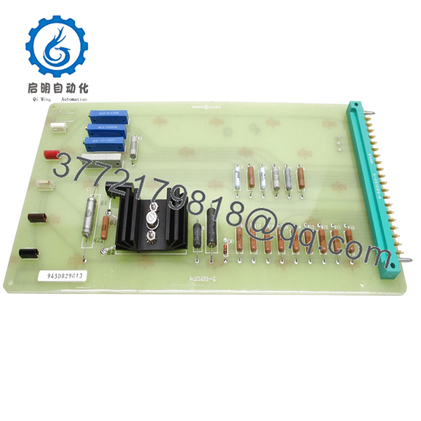
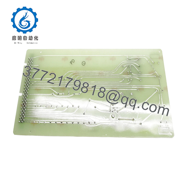
The GE 945D829G13 is a control PCB used in GE excitation systems for generator control applications. It processes analog and digital signals associated with voltage regulation, field control, and system feedback within exciter cabinets.
In operating plants, this board is typically found in EX2000 or earlier excitation systems where stable field control is required. It is retained in service due to long equipment lifecycles, even though the platform itself is considered legacy and no longer in active production.
5. Installation & Configuration Guide
Stage 1: Pre-Installation Preparation (Estimated 10–15 minutes)
- ⚠️ Safety First: Notify operations, isolate generator/exciter system, apply LOTO, and wait at least 5 minutes for stored energy discharge.
- Tools Required: ESD wrist strap, PH1 screwdriver, Fluke 115 multimeter, labeling tags, smartphone.
- Data Backup:
- Record exciter configuration parameters from HMI or controller.
- Photograph board position, connectors, and wiring harnesses.
- Label all connectors clearly before removal.
Stage 2: Removing the Old Module (Estimated 5–10 minutes)
- Open exciter cabinet and identify the board location.
- Disconnect ribbon cables and edge connectors carefully.
- Release retaining clips or mounting screws.
- Slide the board out evenly — avoid flexing the PCB.
- Inspect connectors for oxidation or loose pins.
- ⚠️ Note: Keep the old board for comparison—especially connector orientation and revision markings.
Stage 3: Installing the New Module (Estimated 10 minutes)
- Wear ESD protection before handling.
- Verify model number 945D829G13 and hardware revision.
- Align with card guides and insert evenly into slot.
- Secure with mounting hardware.
- Reconnect all cables firmly — no partial seating.
- Self-Checklist:
- All connectors fully seated
- No cable strain or misalignment
- Board secured in slot
Stage 4: Power-On & Testing (Estimated 10–15 minutes)
- Pre-Power Check: Verify no shorts on power rails and proper grounding.
- Power-On Steps:
- Energize exciter cabinet.
- Observe system status indicators and alarms.
- Check voltage regulation feedback signals.
- Validate field control response under no-load condition.
- Monitor for abnormal heating or noise.
- ⚠️ Troubleshooting Note:
- No response: Check connector seating and signal cables.
- Unstable excitation: Verify feedback signal integrity and grounding.
6. Frequently Asked Questions (FAQ)
Q1: Can this board be hot-swapped?
No. Excitation control systems are not designed for live insertion. Removing or inserting under power can damage both the board and the exciter system. Always shut down and isolate first.
Q2: Is this model obsolete?
Yes. This is a legacy GE excitation board. Most units in circulation are surplus or refurbished. Availability is limited and batch-dependent.
Q3: Is this a direct replacement for all 945D829 series boards?
Not necessarily. The “G13” suffix indicates a specific revision. Other revisions (e.g., Gxx variants) may differ in circuitry or firmware. Always verify against system documentation.
Q4: Will replacing this board affect generator control settings?
The board itself does not store primary control logic, but it interacts with calibration signals. You should verify tuning parameters after installation to avoid voltage instability.
Q5: Why is availability inconsistent?
Because this board is no longer manufactured. Stock comes from surplus inventory or decommissioned systems. Lead times can vary significantly.
Q6: What’s the most common failure cause for this board?
From field experience: capacitor aging and connector degradation. After 15–20 years in service, analog signal drift becomes noticeable.

- 945D829G13
- 945D829G13
SOP Quality Transparency
1. Inbound Inspection & Traceability
- Verified against OEM part numbering and procurement records.
- Serial and revision markings inspected.
- Visual inspection: no PCB warping, no burnt components, intact conformal coating.
- Connector pins checked for wear or oxidation.
2. Live Functional Testing
- Tested in a GE excitation system simulation rack.
- Verified signal processing and interface behavior.
- Analog input/output simulation performed.
- Continuous operation test: 24-hour powered run.
- Monitoring for thermal stability and signal drift.
- Test documentation available upon request.
3. Electrical Parameter Testing
- Insulation resistance >10 MΩ @ 500 V Megger.
- Ground continuity verified.
- Signal path continuity tested.
4. Firmware & Configuration Verification
- Revision and onboard identifiers documented.
- Verified compatibility with EX2000 system interface requirements.
5. Final QC & Packaging
- QC sign-off with traceable inspection report.
- Anti-static ESD packaging.
- Foam-protected industrial carton.
- QC Passed label with inspection date.
Technical Pitfall & Survival Guide
❗ 1. Revision Mismatch (G13 vs Others)
I’ve seen engineers assume all 945D829 boards are interchangeable—they’re not. One plant lost a full day chasing unstable excitation because the revision differed.
Avoidance: Match the exact suffix (G13). Don’t substitute blindly.
❗ 2. Connector Orientation Errors
Ribbon cables in excitation cabinets can be installed incorrectly if forced.
Anecdote: A reversed connector caused immediate fault on startup.
Avoidance: Match orientation from photos. Never force connectors.
❗ 3. Analog Signal Noise Issues
Excitation systems rely heavily on clean analog feedback.
Avoidance: Check shielding and grounding. One bad ground can destabilize voltage regulation.
❗ 4. Power Supply Margin
Older excitation systems often run near PSU limits.
Avoidance: Confirm voltage stability before and after installation. Leave at least 20% headroom.
❗ 5. ESD Damage
These legacy boards are particularly sensitive due to aging components.
Real case: Static discharge caused intermittent faults—not immediate failure, which made diagnosis painful.
Avoidance: Always use ESD protection.


