
 WhatsApp: +86 16626708626
 Email:
  Phone: +86 16626708626
Description
3. Key Technical Specifications
| Parameter | Value |
|---|---|
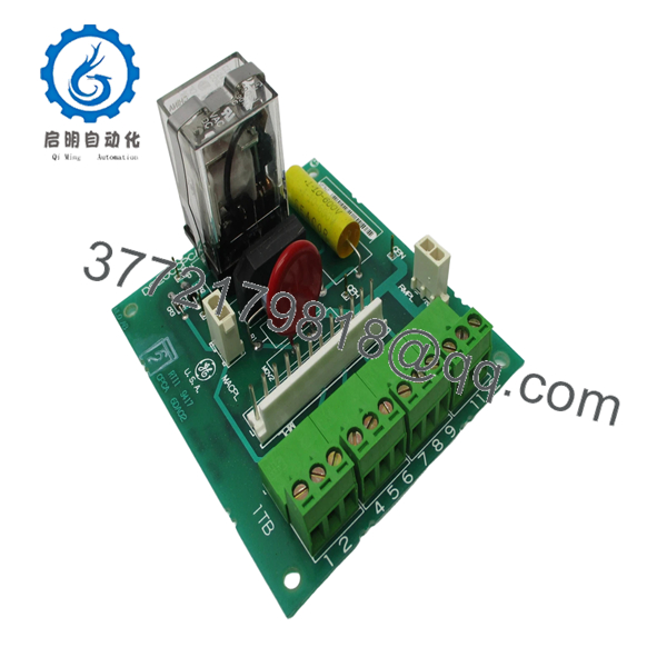
| Product Type | Contactor Pilot Board (CPCA) |
| Series | GE Mark V Speedtronic |
| Function | Contactor coil control and switching |
| Input Voltage | 115 V AC (coil supply) |
| Output Voltage | ~105 V DC (contactor drive) |
| Relay | 24 V DC socket relay |
| Connectors | 1 × 12-pin, 2 × 2-pin |
| Terminal Blocks | 4 blocks (up to 12 signal wires) |
| Communication | Backplane / hardwired signal interface |
| Operating Temperature | −35°C to +65°C |
| Mounting | Rack-mounted PCB |
| Application | Turbine control / EX2000 excitation systems |
4. Product Introduction
The GE DS200CPCAG1A is a Contactor Pilot Board (CPCA) used in the Mark V Speedtronic control system. It manages pilot-level control signals and supplies the necessary voltage to actuate contactor coils within turbine and excitation systems.
In field applications, this board is responsible for reliable switching of contactors tied to critical drive and protection sequences. It converts 115 V AC input into approximately 105 V DC to maintain contactor operation, ensuring stable engagement under load conditions.
5. Installation & Configuration Guide
Stage 1: Pre-Installation Preparation (Estimated 10–15 minutes)
- ⚠️ Safety First: Notify operations, shut down turbine/excitation system, apply LOTO, and wait at least 5 minutes for stored energy discharge.
- Tools Required: ESD wrist strap, PH1 screwdriver, Fluke 115 multimeter, labeling tags, smartphone.
- Data Backup:
- Record system configuration and interlock logic.
- Photograph wiring on terminal blocks (critical).
- Label each wire before removal.
Stage 2: Removing the Old Module (Estimated 5–10 minutes)
- Locate CPCA board in Mark V rack or exciter panel.
- Disconnect terminal wiring — do not pull wires without loosening screws.
- Remove connectors (12-pin and 2-pin plugs).
- Release mounting hardware and slide board out evenly.
- Inspect terminals and connectors for wear or carbonization.
- ⚠️ Note: Terminal wiring errors are one of the top causes of restart failure—keep the old board as reference.
Stage 3: Installing the New Module (Estimated 10 minutes)
- Wear ESD protection before handling.
- Confirm exact model: DS200CPCAG1A (Revision A).
- Insert board into guides and secure mechanically.
- Reconnect all wiring based on labels/photos.
- Ensure terminal screws are tight but not over-torqued.
- Self-Checklist:
- All 12 signal wires correctly landed
- Connectors fully seated
- Board secured and aligned
Stage 4: Power-On & Testing (Estimated 10–15 minutes)
- Pre-Power Check: Verify no short circuits across terminal blocks.
- Power-On Steps:
- Energize control system.
- Observe contactor response (listen for coil engagement).
- Measure output voltage (~105 V DC at coil terminals).
- Verify sequence logic through HMI or control diagnostics.
- Perform functional test of contactor switching.
- ⚠️ Troubleshooting Note:
- Contactor not pulling in → check AC input and DC output conversion.
- Chattering contactor → suspect unstable supply or wiring issue.

- DS200CPCAG1A
- DS200CPCAG1A
6. Frequently Asked Questions (FAQ)
Q1: Can I hot-swap the DS200CPCAG1A?
No. This board directly handles control voltage for contactors. Removing it under power can arc terminals and damage both the board and contactor circuits.
Q2: Is this model obsolete?
Yes. Mark V is a legacy platform. Most available units are surplus or refurbished. Lead times depend heavily on secondary market inventory.
Q3: What is the difference between DS200CPCAG1 and DS200CPCAG1A?
The “A” suffix indicates a functional revision. In practice, it includes minor design updates. Always match the exact suffix unless you confirm interchangeability with GE documentation.
Q4: What does this board actually control?
It drives contactor coils by converting 115 V AC into DC voltage and maintaining coil energization. Without it, contactors will not engage or stay closed.
Q5: Why is wiring such a big concern on this board?
Because it uses terminal blocks instead of plug-and-play connectors. Misplacing even one wire can break interlocks or cause unsafe switching conditions.
Q6: What’s the most common field failure?
Relay wear and terminal overheating. After years of operation, contact resistance increases and causes unstable switching.
SOP Quality Transparency
1. Inbound Inspection & Traceability
- Verified against GE Mark V part numbering format.
- Serial and revision inspected for authenticity.
- Visual inspection: no burnt relay contacts, no PCB discoloration, intact conformal coating.
- Terminal blocks checked for mechanical integrity.
2. Live Functional Testing
- Tested on a GE Mark V simulation rack / exciter panel.
- Verified AC-to-DC conversion under load.
- Relay actuation tested with simulated contactor coil.
- Continuous runtime: 24-hour energized test.
- Voltage output stability monitored.
- Test report available upon request.
3. Electrical Parameter Testing
- Insulation resistance >10 MΩ @ 500 V Megger.
- Ground continuity verified.
- Output voltage calibration checked (~105 V DC).
4. Firmware & Configuration Verification
- No firmware dependency (hardware control board).
- Jumper/settings (if present) documented and photographed.
5. Final QC & Packaging
- QC sign-off with traceable record.
- Anti-static ESD packaging.
- Foam-protected industrial carton.
- QC Passed label with inspection date.
Technical Pitfall & Survival Guide
❗ 1. Wiring Misplacement on Terminal Blocks
This is the number one failure point. I’ve seen a single swapped wire prevent a turbine from starting.
Avoidance: Take clear photos before removal. Label every wire.
❗ 2. Assuming It’s Just a “Relay Board”
It’s not. This board handles voltage conversion and control logic for contactors.
Avoidance: Treat it as a control-critical component, not a simple relay interface.
❗ 3. Revision Confusion (G1 vs G1A)
Technicians often assume revisions are interchangeable. That’s not always safe.
Avoidance: Match the exact part number unless validated.
❗ 4. Power Supply Instability
If upstream supply fluctuates, contactors will chatter.
Real case: A plant blamed the board—root cause was unstable 115 V feed.
Avoidance: Verify supply quality before replacement.
❗ 5. ESD Damage During Handling
These boards include sensitive control circuitry.
Avoidance: Use proper grounding. Static damage may not show immediately—it can fail hours later.


