
 WhatsApp: +86 16626708626
 Email:
  Phone: +86 16626708626
Description
3. Key Technical Specifications
| Parameter | Value |
|---|---|
| Product Type | Drive Control Card (SDCC) |
| Series | GE Mark V Speedtronic |
| Function | Primary drive controller |
| Processor Architecture | 3 microprocessors |
| Memory | Shared RAM accessible by multiple CPUs |
| Communication | Backplane + inter-board connectors |
| Interfaces | Power Supply Interface Board (DC + I/O signals) |
| Diagnostics | 10 LED status/error indicators |
| PCB Coating | Standard conformal coating |
| Operating Environment | Turbine control cabinets |
| Manual Reference | GEI-100029 |
| Revision | A (functional), G (secondary), D (artwork) |
4. Product Introduction
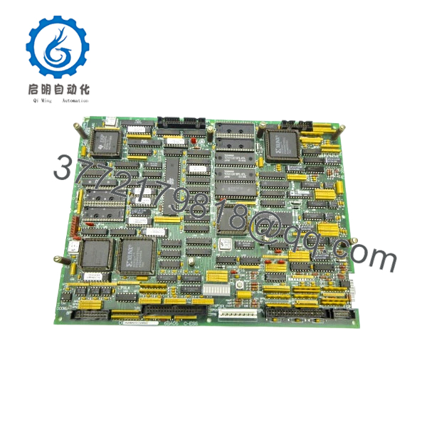
The GE DS200SDCCG4AGD is the main drive control card used in the Mark V Speedtronic turbine control system. It acts as the central processing unit for drive-related functions, coordinating control logic, I/O handling, and communication with auxiliary boards.
In real installations, this board is effectively the “brain” of the drive section. It uses a multi-processor architecture with shared memory to handle parallel control tasks, which is critical for turbine applications requiring deterministic response and fault handling.
5. Installation & Configuration Guide
Stage 1: Pre-Installation Preparation (Estimated 10–15 minutes)
- ⚠️ Safety First: Shut down turbine system, apply lockout/tagout, and wait minimum 5 minutes for DC bus discharge.
- Tools Required: ESD strap, PH1 screwdriver, Fluke 115 multimeter, labeling tags, smartphone.
- Data Backup:
- Backup Mark V configuration via control interface.
- Record slot position and board ID.
- Photograph all connectors and cable routing.
Stage 2: Removing the Old Module (Estimated 5–10 minutes)
- Open drive cabinet and locate SDCC board.
- Disconnect all ribbon cables and connectors carefully.
- Release mounting clips or card guides.
- Pull board straight out — avoid bending.
- Inspect backplane connectors for bent pins or contamination.
- ⚠️ Note: Keep the old board nearby—especially for jumper and revision reference.
Stage 3: Installing the New Module (Estimated 10 minutes)
- Wear ESD protection before handling.
- Confirm exact model: DS200SDCCG4AGD.
- Align with card guides and insert evenly.
- Secure locking mechanism.
- Reconnect all cables per labels/photos.
- Self-Checklist:
- Board fully seated
- All connectors secured
- No pin misalignment
Stage 4: Power-On & Testing (Estimated 10–15 minutes)
- Pre-Power Check: Verify no shorts on supply rails.
- Power-On Steps:
- Energize system.
- Observe LED sequence (left-to-right flashing = normal idle state).
- Connect to control system and verify communication.
- Check drive parameters and system status.
- Run dry test before full load operation.
- ⚠️ Troubleshooting Note:
- LED error code → decode using GEI-100029 manual.
- No comms → check backplane seating or connector mismatch.
6. Frequently Asked Questions (FAQ)
Q1: Can this board be hot-swapped?
No. Mark V boards are not hot-swappable. Removing under power risks backplane damage and system crash.
Q2: Is this model obsolete?
Yes. Mark V is a legacy GE platform. This board is no longer manufactured and is sourced from surplus or refurbished inventory.
Q3: What makes this board critical?
This is the primary drive controller. If it fails, the drive system loses control logic entirely—no partial operation.
Q4: Are all DS200SDCCG4 revisions interchangeable?
Not always. This variant includes specific revisions (A/G/D). Differences can include firmware and memory allocation. Always match full part number.
Q5: What do the LEDs actually indicate?
They display operational status and fault codes. The LED sequence encodes error digits (hundreds, tens, units), which you decode via the manual.
Q6: Why does this board use multiple microprocessors?
Because control tasks are distributed—one handles I/O, another logic, another communication. This improves deterministic timing in turbine control.

- DS200SDCCG4AGD
SOP Quality Transparency
1. Inbound Inspection & Traceability
- Verified against GE part numbering format and revision codes.
- Serial numbers inspected.
- Visual inspection: no PCB warping, no burned components, intact coating.
- Connector pins inspected under magnification.
2. Live Functional Testing
- Tested on a GE Mark V drive simulation rack.
- Verified multi-processor boot sequence.
- LED diagnostics tested (error code simulation).
- Communication with power supply interface board verified.
- Continuous operation: 24-hour runtime test.
- Test report available (video/photos upon request).
3. Electrical Parameter Testing
- Insulation resistance >10 MΩ @ 500 V Megger.
- Ground continuity verified.
- Voltage rails checked (+5 V, +15 V testpoints).
4. Firmware & Configuration Verification
- Firmware/revision identifiers recorded.
- Memory integrity checked.
- Jumper settings documented.
5. Final QC & Packaging
- QC sign-off with traceable record.
- Anti-static ESD packaging.
- Foam-protected industrial carton.
- QC Passed label with inspection date.
Technical Pitfall & Survival Guide
❗ 1. Firmware / Revision Mismatch
I’ve seen drives fail to initialize because the SDCC revision didn’t match the system firmware.
Avoidance: Always document the original board revision before replacement.
❗ 2. Connector Misalignment
This board has multiple interconnects—one misaligned plug can take down the whole drive.
Avoidance: Reconnect methodically. Don’t rush.
❗ 3. Misinterpreting LED Codes
Technicians often ignore LED diagnostics. That’s a mistake.
Anecdote: A team spent hours troubleshooting wiring—the LED code clearly pointed to a RAM fault.
Avoidance: Always decode LED patterns first.
❗ 4. Power Supply Dependency
This board relies heavily on the Power Supply Interface Board.
Avoidance: If SDCC fails repeatedly, check upstream power board—not just the SDCC.
❗ 5. ESD Damage
Multi-processor boards are highly sensitive.
Real case: Static damage caused intermittent faults—not immediate failure.
Avoidance: Always use proper grounding.


