
 WhatsApp: +86 16626708626
 Email:
  Phone: +86 16626708626
Description
3. Key Technical Specifications
| Parameter | Value |
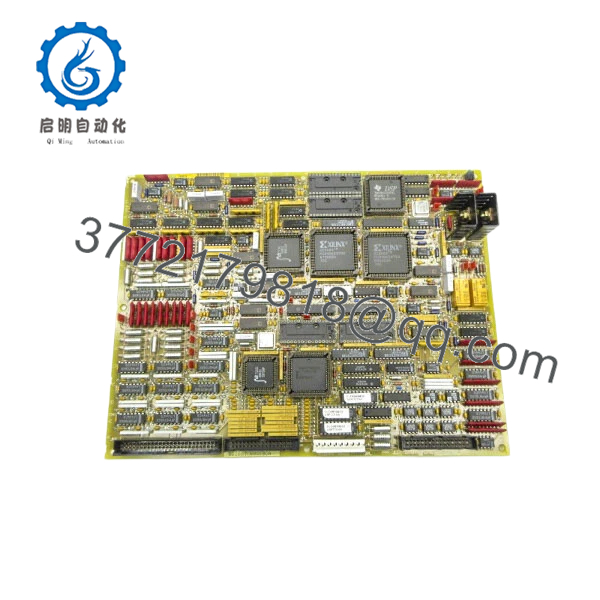
| Product ID | DS200TCQBG1BCA |
| System Series | Speedtronic Mark V |
| Board Acronym | TCQB |
| Redundancy | Support for TMR (Triple Modular Redundant) Systems |
| I/O Type | Analog Input / Output Signal Conditioning |
| Communication | High-speed ribbon cable interface to Control Core |
| Operating Temp | 0 to 60°C (32 to 140°F) |
| Dimensions | 10.5 in x 7.25 in |
| Revision | 1BCA (Group 1, Revision BCA) |
4. Product Introduction
The GE DS200TCQBG1BCA is a critical Analog I/O Board (TCQB) located within the GE Speedtronic Mark V control rack. This board serves as an essential expansion and conditioning layer for analog signals, feeding vital data to the system’s control processors. It typically works in conjunction with the STCA (Source Terminal) and TCCA (Processor) boards to manage data voting and signal integrity.
In a TMR architecture, the TCQB board is pivotal for ensuring that the R, S, and T cores receive synchronized and accurately scaled analog inputs. For field engineers, the TCQB is often the focus when troubleshooting analog measurement discrepancies or “Voter Mismatch” alarms that suggest a single core is seeing “ghost” data compared to the other two.
5. Installation & Configuration Guide
Stage 1: Pre-Installation Preparation (Estimated Time: 15 mins)
- ⚠️ Safety First: This board handles critical analog feedback. Replacing it while the unit is online can trigger a “Voter Failure” if the new board is not seated perfectly, potentially causing a unit trip. If possible, perform this swap during a scheduled shutdown.
- Tools Required: ESD wrist strap, PH1 screwdriver, and a non-conductive jumper tool.
- Data Backup: Ensure you have access to the
TC2000.DATconfiguration files and document all physical hardware jumpers (J) and DIP switches (SW).
Stage 2: Removing the Old Module (Estimated Time: 10 mins)
- Ground yourself using an ESD strap.
- Label and disconnect the ribbon cables (typically connected to the top and sides of the board). ⚠️ Warning: Use the pull-tabs; pulling on the ribbon wires can cause micro-fractures in the cable housing.
- Remove the mounting screws from the card cage or standoffs.
- Carefully extract the board, keeping it level to avoid snagging neighboring boards.
Stage 3: Installing the New Module (Estimated Time: 15 mins)
- Configuration Clone (Critical): The TCQB board has several jumpers that define signal scaling and hardware addressing. Mirror the jumper positions from the old board exactly. Failure to do so will result in “Hardware Configuration Mismatch” errors upon boot.
- Align the board with the rack slots and push firmly until the backplane connectors engage.
- Secure the mounting screws and reconnect the ribbon cables.
- Self-Checklist: [ ] Jumpers match original, [ ] Ribbon cables locked, [ ] Grounding contact secure.
Stage 4: Power-On & Testing (Estimated Time: 20 mins)
- Apply control power to the specific core.
- Observe the diagnostic LEDs on the board and the <I> station / HMI.
- Check for any “Analog Input Fault” or “Voter Conflict” alarms.
- Perform a loop check on a known analog input (e.g., a temperature or pressure point) to verify the board is scaling the signal correctly.
- ⚠️ Troubleshooting Note: If the board is not seen by the system, check the ID jumpers (typically J1/J2) to ensure the core address is set correctly for R, S, or T.
- DS200TCQBG1BCA
6. Frequently Asked Questions (FAQ)
Q: Can I use a DS200TCQBG1BCA to replace an older “AAA” version?
A: Generally, yes. The “BCA” suffix is a later revision of the Group 1 (G1) series. GE designed these to be backward compatible. However, you must meticulously copy the jumper settings, as newer revisions occasionally have additional jumper pins that must be set to “Neutral” or “Default” to match older system configurations.
Q: Why am I getting a “Voter Mismatch” alarm after installing this board?
A: This usually happens if the calibration or jumper settings on the new TCQB don’t perfectly match the boards in the other two cores. Check the precision of your analog inputs. If one core is off by even 1-2%, the TMR logic will flag it. Verify that your jumpers for signal gain/attenuation are identical across all cores.
Q: Is this board “Hot-Swappable”?
A: In a TMR system, you can theoretically power down a single core and swap this board while the other two cores keep the turbine running. However, this is high-risk. If the remaining cores detect a disturbance on the common I/O bus during the swap, the turbine will trip. I always recommend a full system shutdown for TCQB replacements if the unit’s availability permits.
Q: Does this board require a software download?
A: The TCQB board is hardware-configured via jumpers. While the Mark V system as a whole uses software configurations, the TCQB itself doesn’t typically require a specific “firmware flash” at the board level. It will work as soon as the core recognizes the hardware address and jumpers.
Q: What is the benefit of “New Surplus” over a used board?
A: Analog boards like the TCQB rely on precise resistor networks and capacitors. Used boards have been “cooked” in a hot control cabinet for decades, which causes component values to drift. New Surplus boards provide “factory-fresh” accuracy, which is essential for maintaining the tight voting tolerances required by the Mark V.


